Hybrid vehicle

a hybrid vehicle and hybrid technology, applied in the direction of vehicle sub-unit features, battery/fuel cell control arrangement, transportation and packaging, etc., can solve the problems of insufficient acceleration force after upshifting, driver may feel discomfort in not acquiring such a feeling of speed change, etc., to minimize charging and discharging of batteries, reduce the effect of power storage ratio of batteries

Active Publication Date: 2017-11-23
TOYOTA JIDOSHA KK
View PDF7 Cites 9 Cited by
  • Summary
  • Abstract
  • Description
  • Claims
  • Application Information

AI Technical Summary

Benefits of technology

[0010]In the hybrid vehicle according to the aspect, the electronic control unit may be configured to set the correction driving force to be smaller as the rotation speed of the engine becomes lower. According to the hybrid vehicle of the aspect, it is possible to smooth the change of the driving force in consideration of fuel efficiency when the rotation speed of the engine is low.
[0011]In the hybrid vehicle according to the aspect, the electronic control unit may be configured to set the correction driving force to be smaller as a power storage ratio which is a ratio of dischargeable power to full capacity of the battery becomes lower. According to the hybrid vehicle of the aspect, it is possible to minimize charging and discharging of the battery to protect the battery when the power storage ratio of the battery is low.
[0012]In the hybrid vehicle according to the aspect, the electronic control unit may be configured to set the correction driving force to be smaller when a temperature of the battery is not in an appropriate temperature range than when the temperature of the battery is in an appropriate temperature range. According to the hybrid vehicle of the aspect, it is possible to minimize charging and discharging of the battery to protect the battery when the temperature of the battery is not in an appropriate temperature range.
[0013]In the hybrid vehicle according to the aspect, the electronic control unit may be configured to set the correction driving force to gradually decrease when a predetermined time elapses after upshifting. According to the hybrid vehicle of the aspect, it is possible to prevent the base driving force from being greatly corrected over the predetermined time after upshifting and to suppress overdischarging of the battery.

Problems solved by technology

In this case, since the driver generally has a feeling of a change in speed in which the rotation speed of the engine decreases due to the upshift of the stepped gearshift as a driving feeling, the driver may feel discomfort in not acquiring such a feeling of a change in speed.
However, in this case, since the driving force output to the drive shaft depends on engine characteristics, an acceleration force after upshifting may not be sufficient.
Such a problem is true when a virtual speed level shift is performed in a hybrid vehicle not including a stepped gearshift.

Method used


Image

  • Hybrid vehicle
  • Hybrid vehicle
  • Hybrid vehicle

Examples


first embodiment

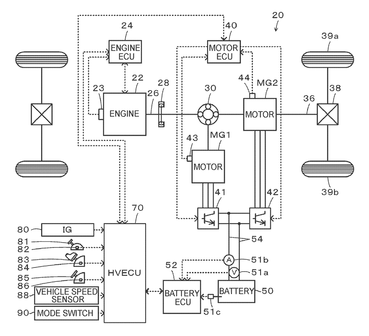
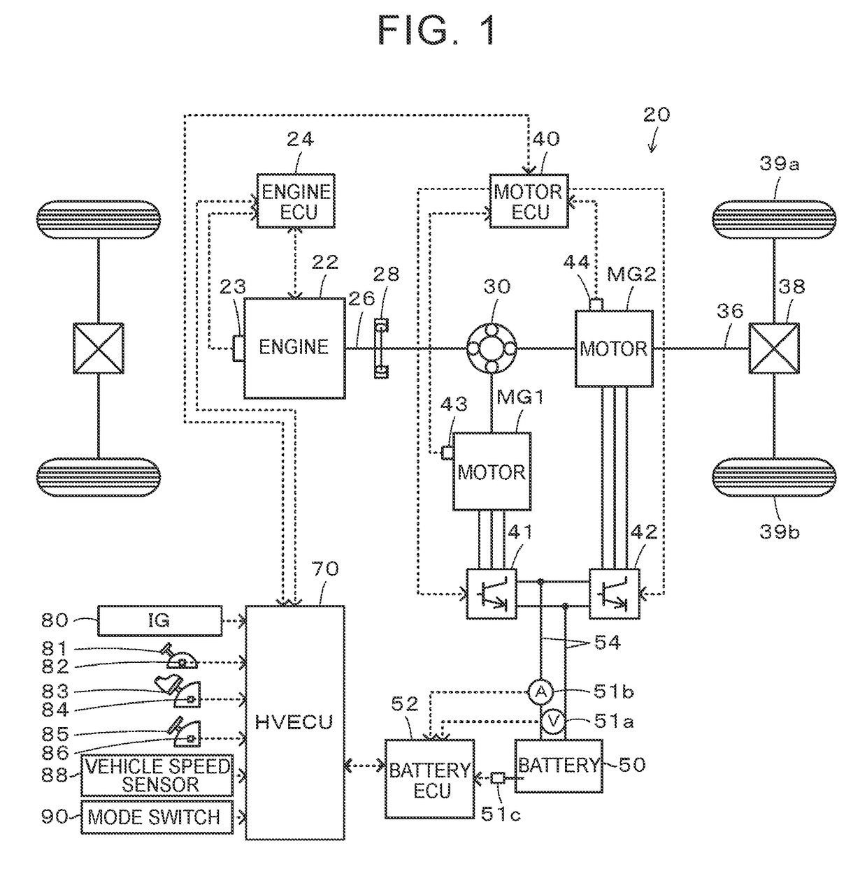
[0050]The hybrid vehicle 20 having the above-mentioned configuration travels in any one of a plurality of driving modes including a hybrid driving (HV driving) mode and an electrical driving (EV driving) mode. Here, the HV driving mode is a mode in which the vehicle travels using power from the engine 22 and power from the motors MG1 and MG2 while operating the engine 22. The EV driving mode is a mode in which the vehicle travels using power from the motor MG2 without operating the engine 22.

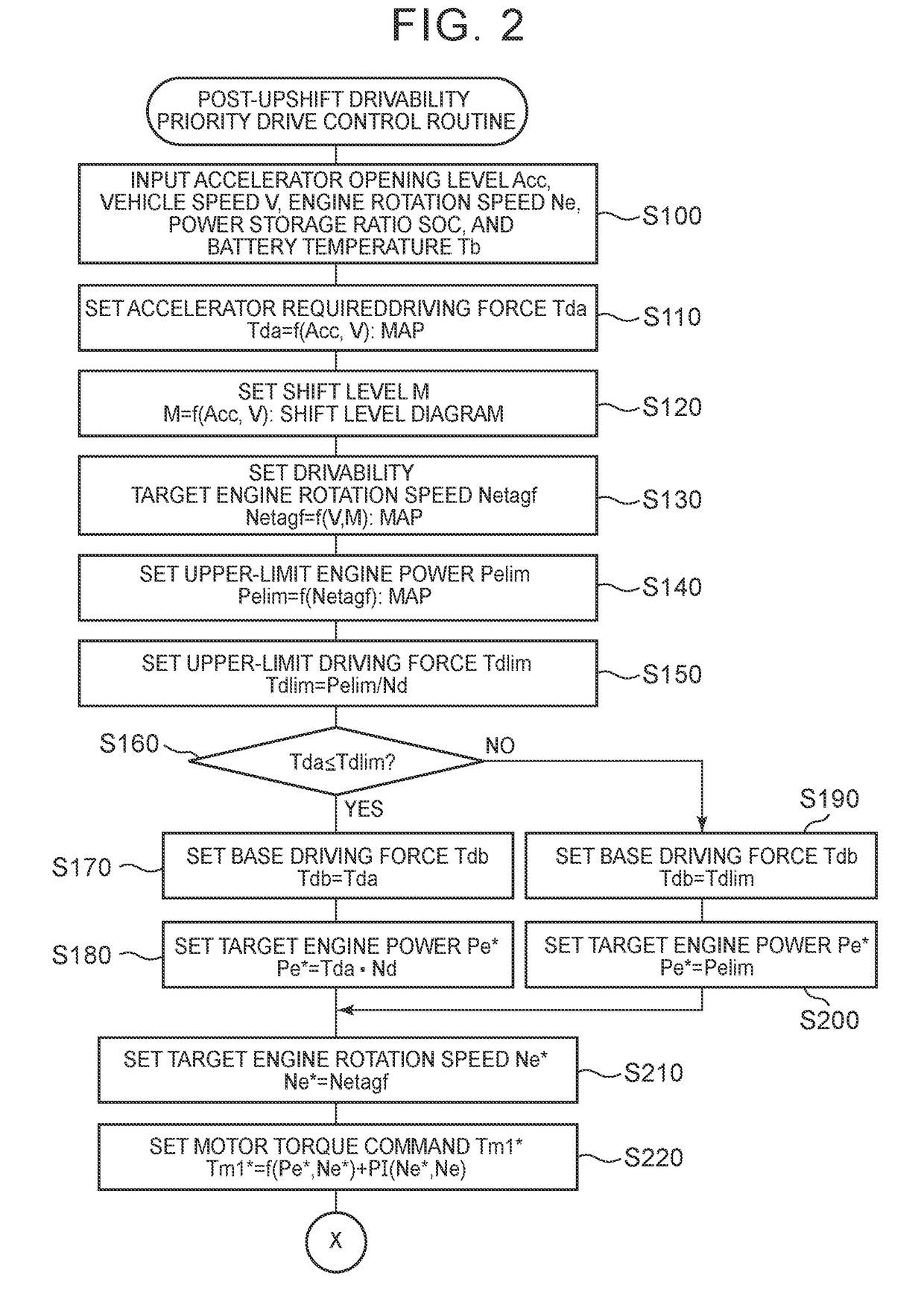
[0051]The operation of the hybrid vehicle 20 having the above-mentioned configuration, particularly, the operation when the automatic gearshift of six virtual shift stages upshifts during travel in a state in which the driving feeling priority mode is selected by the mode switch 90, will be described below. FIGS. 2 and 3 are flowcharts illustrating an example of a post-upshift drivability priority drive control routine which is performed by the HVECU 70 when the driving feeling priority mode is...

second embodiment

[0088]In the hybrid vehicle 120 when the shift position is the D position in the driving feeling priority mode, the post-upshift drivability priority drive control routine illustrated in FIGS. 20 and 21 are performed. The post-upshift drivability priority drive control routine illustrated in FIGS. 20 and 21 is the same as the post-upshift drivability priority drive control routine illustrated in FIGS. 2 and 3, except for Step S120C of setting an actual shift stage Ma as well as the shift stage M, Steps S310C and 5340C of setting the torque command Tm2* of the motor MG2 using a gear ratio Gr of the actual shift stages Ma of the gearshift 130, and Steps S320C and 5350C of transmitting the actual shift stage Ma to the gearshift 130 when transmitting the target engine power Pe* or the target engine rotation speed Ne*. Accordingly, the same processes in the post-upshift drivability priority drive control routine illustrated in FIGS. 20 and 21 as in the post-upshift drivability priority ...


PUM


Abstract

A hybrid vehicle includes an engine, a first motor, a planetary gear mechanism, a second motor, a battery, and an electronic control unit. The electronic control unit is configured to: set a shift stage based on a depression amount of an accelerator and a vehicle speed or a driver's operation; set a base driving force based on the degree of the depression amount of the accelerator, the vehicle speed, and a target rotation speed; set a correction driving force such that the correction driving force increases with an increase in elapsed time after upshifting or an increase in the vehicle speed after upshifting when the shift stage upshifts; and control the engine, the first motor, and the second motor such that a driving force obtained by correcting the base driving force using the correction driving force is output to the drive shaft.

Description

CROSS-REFERENCE TO RELATED APPLICATIONS[0001]This application claims priority to Japanese Patent Application No. 2016-099381 filed on May 18, 2016, which is incorporated herein by reference in its entirety.BACKGROUND1. Technical Field[0002]The present disclosure relates to a hybrid vehicle.2. Description of Related Art[0003]In the related art, a hybrid vehicle in which a rotary element, which is connected to a second motor, of a planetary gear mechanism of which three rotary elements are connected to an engine, a first motor, and the second motor is connected to a drive shaft connected to vehicle wheels via a stepped gearshift has been proposed (for example, see Japanese Patent Application Publication No. 2014-144659 (JP 2014-144659 A)). Driving of such a vehicle is basically controlled as follows. First, a required driving force is set based on a depression amount of an accelerator pedal by a driver and a vehicle speed, and the required driving force is multiplied by a rotation spe...

Claims


Application Information

Patent Timeline
Patent Type & Authority Applications(United States)
IPC IPC(8): B60W20/10B60W10/06B60K6/365B60W10/115B60W20/30B60W30/18B60L11/18B60W10/08B60L50/16
CPCB60W20/10B60Y2300/91B60W10/06B60W10/08B60W10/115B60W20/30B60W30/18027B60L11/1872Y10S903/91B60Y2200/92B60Y2400/73Y10S903/93B60W2540/10B60W2520/10B60W2510/1005B60W2710/0644B60W2710/08B60W2710/1005B60Y2300/43B60Y2300/60B60Y2300/70B60K6/365B60W20/00B60K6/445B60K6/547B60W50/06B60L58/25Y02T10/62Y02T10/70Y02T10/72
Inventor KATO, SHUNYASUGAI, MASAYA
Owner TOYOTA JIDOSHA KK
Why Eureka
Try Eureka