Uniflow engine with fluid flow arrangement

a technology of fluid flow and engine, applied in the direction of liquid fuel engines, machines/engines, mechanical equipment, etc., can solve the problems of adversely affecting emissions, achieve the effects of minimizing heat transfer, minimizing intake air turbulence, and minimizing work needed

Active Publication Date: 2017-11-23
VOLVO LASTVAGNAR AB
View PDF7 Cites 6 Cited by
  • Summary
  • Abstract
  • Description
  • Claims
  • Application Information

AI Technical Summary

Benefits of technology

[0005]It is desirable to minimize the turbulence of the intake air entering a ported cylinder in order to minimize heat transfer, minimize work

Problems solved by technology

However, imparting swirl to the incoming charge requires a certain amount of energy, increasing pumping work, results in high heat transfer to the cylinder walls, causes mixing of the fresh charge with the exhaust gases remaining in the cylinder, and may entrain lubricating oil from the walls, adversely aff

Method used


Image

  • Uniflow engine with fluid flow arrangement
  • Uniflow engine with fluid flow arrangement
  • Uniflow engine with fluid flow arrangement

Examples


Embodiment Construction

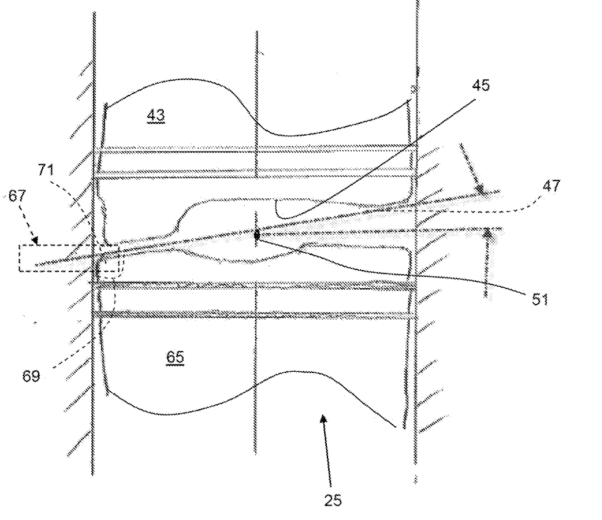
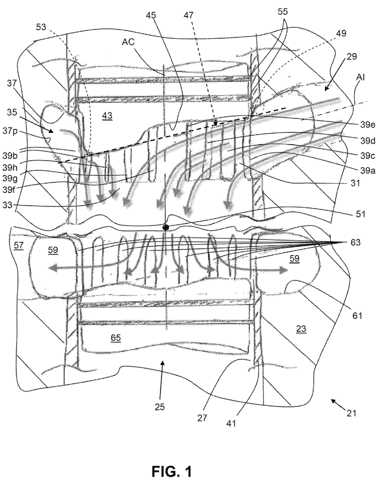
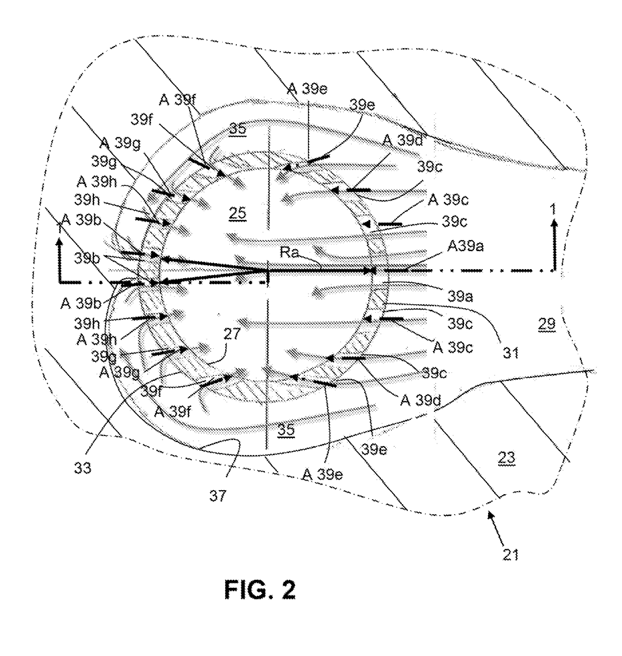
[0012]FIGS. 1-3 shows a portion of a ported uniflow engine 21 with a fluid flow arrangement according to an aspect of the present invention. The uniflow engine 21 can comprise an engine block 23 or other structure in which a cylinder 25 (i.e., at least one) having a cylinder wall 27 is provided. The cylinder 25 is ordinarily circularly cylindrical, but may have other shapes. FIGS. 1-3 show an opposed piston engine 21, however, it will be appreciated that the invention is applicable to a single piston engine 21′ as seen in FIG. 4. The opposed piston engine 21 is shown with the cylinder oriented such that the intake is at the top and the exhaust is at the bottom, while the single piston engine 21′ is shown with cylinder oriented such that the intake is at the bottom and the exhaust is at the top, however, in either case, the orientation of the intake and exhaust at the top or the bottom may be reversed. For purposes of discussion, structures of the opposed piston engine 21 will be des...


PUM


Abstract

A uniflow engine includes a cylinder having a cylinder wall, an inlet channel, an extension of a central axis of the inlet channel first intersecting the cylinder wail in a first portion of the cylinder and next intersecting the cylinder wail in a second portion of the cylinder opposite the first portion of the cylinder, an intake air gallery, the intake air gallery having a gallery wall and being in flow communication with the inlet channel, and a plurality of intake ports extending between the cylinder wail and the gallery wall, at least some of the intake ports having different areas at the cylinder wall measured perpendicular to longitudinal axes of the intake ports, and wherein an area of at least one in take port in the first portion of the cylinder is larger than an area of at least one intake port in the second portion of the cylinder.

Description

BACKGROUND AND SUMMARY[0001]The present invention relates generally to uniflow engines and, more particularly, to arrangements for scavenging of such engines.[0002]Most ported engines, which typically operate on the 2-stroke cycle, induce a high degree of swirl to the incoming air charge in order to maximize the available surface area of the intake port band for intake charge flow, and therefore reduced pumping work, as well as to assure high turbulence for good combustion. However, imparting swirl to the incoming charge requires a certain amount of energy, increasing pumping work, results in high heat transfer to the cylinder walls, causes mixing of the fresh charge with the exhaust gases remaining in the cylinder, and may entrain lubricating oil from the walls, adversely affecting emissions. In addition, filling of a 2-stroke cylinder depends on the pressure difference between intake and exhaust ports (valves), not the absolute flow restriction of the intake system, and intake por...

Claims


Application Information

Patent Timeline
IPC IPC(8): F02B25/08F02B75/28F02B25/04
CPCF02B25/08F02B25/04F02B75/28F02B23/104F02F1/22Y02T10/12F02B2720/236
Inventor MORTON, RICHARD KELLOGG
Owner VOLVO LASTVAGNAR AB
Why Eureka
Try Eureka