Air umbrella device

a technology of air umbrella and umbrella, which is applied in the direction of umbrellas, lighting and heating devices, heating types, etc., can solve the problems of consuming considerable labor and costs, requiring a considerable installation cost, and driving and managing the shading apparatus

Active Publication Date: 2017-11-23
SHIN SANG HO
View PDF6 Cites 3 Cited by
  • Summary
  • Abstract
  • Description
  • Claims
  • Application Information

AI Technical Summary

Benefits of technology

[0005]Therefore, the present invention has been made in view of the above problems, and it is an object of the present invention to provide an air umbrella apparatus capable of protecting a predetermined area from rain or snow by forming an air curtain via the suction and ejection of air without needing to fold or unfold an awning.
[0007]In accordance with one aspect of the present invention, the above and other objects can be accomplished by the provision of an air umbrella apparatus including an air suction pipe vertically disposed on a ground and having an air suction hole formed in an upper end thereof, a water collection pipe disposed concentrically with the air suction pipe so as to accommodate the air suction pipe therein, a water-collection-inducing pipe being coupled to an upper end of the water collection pipe so as to guide rain or snow downward, an exhaust pipe disposed concentrically with the water collection pipe so as to accommodate the water collection pipe therein, an exhaust-guiding pipe being coupled to an upper end of the exhaust pipe so as to guide air outward, a communication pipe coupled to lower ends of the air suction pipe, the water collection pipe, and the exhaust pipe so as to communicate the air suction pipe and the exhaust pipe with each other, and a blower disposed between the exhaust pipe and the water collection pipe so as to introduce the air through the air suction pipe and exhaust the air through the exhaust pipe, wherein the air exhausted through the exhaust-guiding pipe forms an air curtain having a predetermined area at an upper side of the exhaust-guiding pipe, thereby preventing the rain and snow from falling from the exhaust-guiding pipe.
[0014]In accordance with another aspect of the present invention, there is provided an air umbrella apparatus including an air suction pipe vertically disposed on a ground and having an air suction hole formed in an upper end thereof, a water collection pipe disposed concentrically with the air suction pipe so as to accommodate the air suction pipe therein, a water-collection-inducing pipe being coupled to an upper end of the water collection pipe so as to guide rain or snow downward, an exhaust pipe disposed concentrically with the water collection pipe so as to accommodate the water collection pipe therein, an exhaust-guiding pipe being coupled to an upper end of the exhaust pipe so as to guide air outward, a communication pipe coupled to lower ends of the air suction pipe, the water collection pipe, and the exhaust pipe so as to communicate the air suction pipe and the exhaust pipe with each other, and an outer blower installed under a ground and connected to the exhaust pipe via a blower pipe so as to introduce the air through the air suction pipe and exhaust the air through the exhaust pipe, wherein the air exhausted through the exhaust-guiding pipe forms an air curtain having a predetermined area at an upper side of the exhaust-guiding pipe, thereby preventing the rain and snow from falling from the exhaust-guiding pipe.
[0015]In accordance with a further aspect of the present invention, there is provided an air umbrella apparatus including an air suction pipe vertically disposed on a ground and having a suction hole formed in an upper end thereof, into which outside air is suctioned, a water collection pipe disposed concentrically with the air suction pipe so as to accommodate the air suction pipe therein, a water-collection-inducing pipe being coupled to an upper end of the water collection pipe so as to guide rain or snow inward, an exhaust pipe disposed concentrically with the water collection pipe so as to accommodate the water collection pipe therein, an exhaust-guiding pipe being coupled to an upper end of the exhaust pipe so as to guide inside air outward, a communication pipe accommodated inside the water collection pipe and coupled to a lower end of the air suction pipe so as to move the outside air that has passed through the air suction pipe to a space between the water collection pipe and the exhaust pipe, a blower rotatably provided at a lower side of the exhaust pipe so as to form an air stream so that the outside air is introduced through the air suction pipe, and thereafter the inside air is exhausted through the exhaust-guiding pipe, and an air guiding unit disposed between the blower and the water collection pipe and configured to guide the inside air that has passed through the blower to a space between the exhaust-guiding pipe and the water-collection-inducing pipe, wherein the inside air exhausted through the exhaust-guiding pipe forms an air curtain having a predetermined area at an upper side of the exhaust-guiding pipe, thereby preventing the rain and snow from falling from the exhaust-guiding pipe.

Problems solved by technology

Conventional shading apparatuses vary in size depending on the installation place thereof, and require a considerable cost for installation.
Thereby, considerable labor and costs are consumed for the driving and management of the shading apparatus.

Method used


Image

  • Air umbrella device
  • Air umbrella device
  • Air umbrella device

Examples


Embodiment Construction

[0078]To assist sufficient understanding of the present invention, exemplary embodiments of the present invention will be described below with reference to the accompanying drawings. The embodiments of the present invention may be altered in various ways, and the scope of the present invention should not be construed to be limited to the embodiments of the present invention, which are described below in detail. The embodiments are provided to more completely explain the present invention to one of ordinary skill in the art. Thus, the shape and the like of elements may be exaggerated in order to clarify the description. It should be noted that the same reference numbers will be used throughout the drawings to refer to the same or like parts. A detailed description of known functions or configurations incorporated herein will be omitted when it may make the subject matter of the disclosure rather unclear.

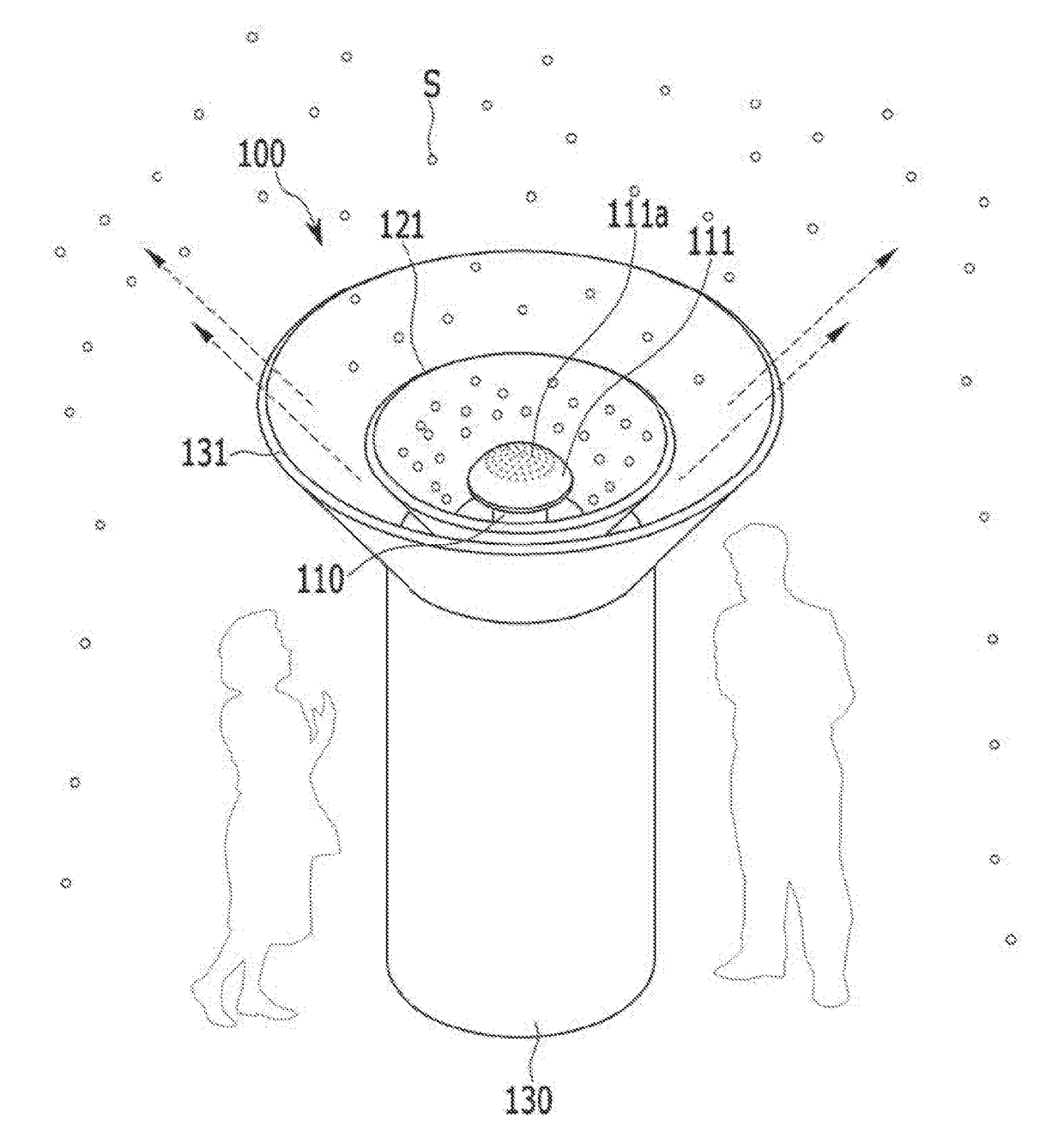
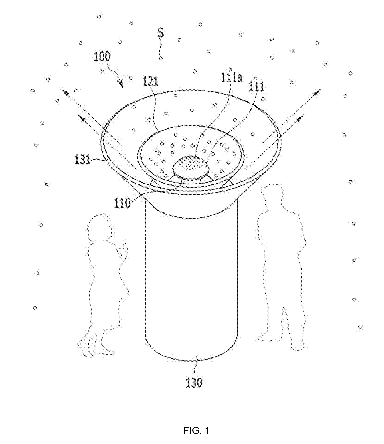
[0079]FIG. 1 is a perspective view illustrating the state in which an air umbrell...


PUM


Abstract

Disclosed is an air umbrella apparatus including an air suction pipe having an air suction hole in an upper end thereof, a water collection pipe disposed concentrically with the air suction pipe and having an upper end coupled to a water-collection-inducing pipe for guiding rain or snow downward, an exhaust pipe disposed concentrically with the water collection pipe and having an upper end coupled to an exhaust-guiding pipe for guiding air outward, a communication pipe coupled to the air suction pipe, the water collection pipe, and the exhaust pipe for communicating the air suction pipe with the exhaust pipe, and a blower disposed between the exhaust pipe and the water collection pipe for the introduction and exhaust of air. The exhausted air forms an air curtain having a predetermined area above the exhaust-guiding pipe, thereby preventing rain and snow from falling from the exhaust-guiding pipe.

Description

BACKGROUND OF THE INVENTIONField of the Invention[0001]The present invention relates to an air umbrella apparatus, and more particularly, to an air umbrella apparatus capable of protecting a predetermined area in an open space having no roof from rain or snow via the suction and ejection of air without a separate awning in the event of rain.Description of the Related Art[0002]In places such as, for example, a bus stop, a public building, and the outside of a restaurant, a shading apparatus is installed in order to block, for example, rain and snow. Such a shading apparatus is kept in a folded state when there is no rain or snow, and is used in an unfolded state when rain or snow falls.[0003]An example of a conventional shading apparatus is disclosed in Korean Patent Registration No. 10-0662106, which is titled “Shading Apparatus and Manufacturing Method thereof”.[0004]Conventional shading apparatuses vary in size depending on the installation place thereof, and require a considerabl...

Claims


Application Information

Patent Timeline
Patent Type & Authority Applications(United States)
IPC IPC(8): F24F9/00
CPCF24F2009/007F24F9/00A45B23/00A45B25/28A45B2200/1036A45B2200/1009E04H15/00E04H1/00E04H1/1211
Inventor SHIN, YOUNG CHEOL
Owner SHIN SANG HO
Why Eureka
Try Eureka