Brake test stand

a test stand and brake technology, applied in the direction of machine parts testing, force/torque/work measurement apparatus, structural/machine measurement, etc., can solve the problems of low mechanical energy stored in the system, drop in the rotational speed of the system, etc., to achieve constant rotational speed, reduce load torque of load generator, reduce load torque

Active Publication Date: 2017-11-23
CREDIT SUISSE
View PDF0 Cites 5 Cited by
  • Summary
  • Abstract
  • Description
  • Claims
  • Application Information

AI Technical Summary

Benefits of technology

[0007]Furthermore, it is provided that the load torque of the load generator is increased by the controller time-dependently corresponding to a ramp prior to testing of the brake. The control and regulation of the load torque of the load generator is taken over by an automatically operating controller. In this case, the load torque of the load generator of the brake is continuously increased over time until the desired load torque is reached for testing of the brake. The load torque causes an equal but opposite driving torque of the drive motor. The increase of the load torque over time can correspond to various mathematical functions or ramps. In this way the increase can be done linearly, for example, where the method according to the invention is not limited, however, to this linear time function.
[0008]Cleverly it is provided that the energy made available by the drive motor is converted during the test where the load torque generated by the load generator is reduced or switched off during the testing of the brake. From the start of the brake operation the energy made available by the drive motor is converted by the brake. This energy is mostly converted into heat. From the start of the conversion of the energy of the drive motor by the brake, the load torque of the load generator is reduced or turned off. This reduction of the load torque is a result of the torque equilibrium which is required in order to guarantee a constant rotational speed of the test stand. With the activation of the brake there is generated a braking moment not previously available which counteracts the driving torque of the drive motor. Prior to braking the load torque of the load generator counteracts alone the driving torque. With the addition of the braking torque, therefore, the load torque must be reduced by the amount of the brake torque to maintain a constant rotational speed. If the braking torque is equal to the load torque prior to braking, the load generator is switched off completely. Since torque and energy are physically coupled via the rotational speed, equivalent relationships are valid for the energies acting in the system (kinetic energy of the drive motor, energy converted in the load generator, energy converted in the brake) such as those described for the ratio of the torques. Therefore, the energy converted in the load generator is reduced after the start of the braking operation by the amount of energy converted in the brake in order to remain in balance with the kinetic energy of the drive motor.
[0009]Furthermore it is provided in a favourable manner that the rotational speed of the drive motor and the load torque of the load generator are controlled by the controller during the testing of the brake according to the conversion of the energy at the brake. As already shown, there is a physical relationship between the acting torques, the rotational speed and the energy in the system. The conversion of a certain amount of energy at the brake is a requirement in checking the brake. Other variables in the system, such as the load torque of the load generator, driving torque and rotational speed of the drive motor, etc. are automatically controlled by the controller according to known physical relationships with the converted braking energy. The controller processes input signals of various sensors to the respective manipulated variables for the components load generator and drive motor, so that the conversion of energy at the brake meets the requirements of the task of testing. Advantageously, it is provided that the rotational speed of the drive motor is controlled to be constant until the brake is tested by keeping all effective torques of the drive motor, the load generator and the brake in balance. A constant rotational speed of the drive motor and thus a constant speed of the test brake during the start of braking is also important for a realistic simulation. Especially the transition between the action of the load generator and the activated brake is crucial here. In order to regulate a constant speed during this transition the controller is referring back to the signals from the rotational speed and torque sensors. If subtlest changes in the rotational speed are detected by the controller here, control signals to the components load generator and drive motor are immediately sent automatically to affect their acting torques and to keep the rotational speed of the brake constant via a balance of driving torque, load torque and braking torque.
[0010]In a further preferred embodiment, it is provided that during testing of the brake, data on braking behavior which enable an evaluation of the brake to be tested is processed by the controller and recorded by the driver simulation memory. The controller has inputs from various sensors. These may be, for example, torque and / or rotational speed sensors. The values determined via these sensors are stored by the controller in a driving simulation memory. In particular, torque and rotational speed values in combination with time values allow for an accurate assessment of operations that take place at the brake during the test. Of course, other data obtained during the testing of the brake can be recorded. Possible measures could be, for example, the temperature at different points of the brake or mechanical stress levels at the brake or its suspension. By saving the test data, an evaluation of the tested brake can also take place at another time or, when transmitting the data via a data interface, at another location. Measurement values of various brakes or different levels of the development of brakes can be easily be compared electronically with one another.
[0011]Furthermore, it is advantageously provided in the proposal that in the driving simulation memory at least one route profile information is stored and the controller determines from this route profile information a temporal progress of torque and rotational speed, which is to be applied in the testing phase, after start of the test, on the brake and these parameters are transmitted to the drive motor. The term route profile information represents a data set that includes all required properties of a test track to be simulated. These are primarily data on the times and durations of braking operations to be performed. In addition to this time information, data related to the kinetic energy of the vehicle to be converted by the brake as well as the wheel rotational speed applied at the time of braking belongs also to the route profile information. The controller determines from this route profile information the temporal progress of torque and rotational speed required for testing the brake on the test stand. During testing of the brake, the corresponding manipulated variables for mapping of the route profile on the test stand are transmitted by the controller to the drive motor and the load generator and their conversion into a control loop is monitored. Of course, more different route profile information can be stored in the driving simulation memory. This route profile information can then be selected at the controller prior to performing of a test method according to the invention. Thus it is possible to select and carry out the most varied simulated test tracks via software without mechanical modifications.

Problems solved by technology

The mechanical energy stored in the system is also low due to the low moved masses.
Therefore, the result would be a drop in the rotational speed of the system until the required kinetic energy is again available because of the readjusted driving torque.

Method used


Image

  • Brake test stand

Examples


Embodiment Construction

[0029]In the figures identical or corresponding elements are each identified by the same reference numerals and will therefore, if inadequate, not be described again. The disclosures contained throughout the description can be applied accordingly to the same parts with the same reference numbers or same component names. Also, the positions chosen for purposes of the description, such as top, bottom, side, etc., relate to the drawing specifically being described and illustrated and are to be appropriately transferred to the new position in case of change in position. Furthermore, individual features or combinations of features from the various embodiments shown and described can represent in themselves independent or inventive solutions or solutions according to the invention.

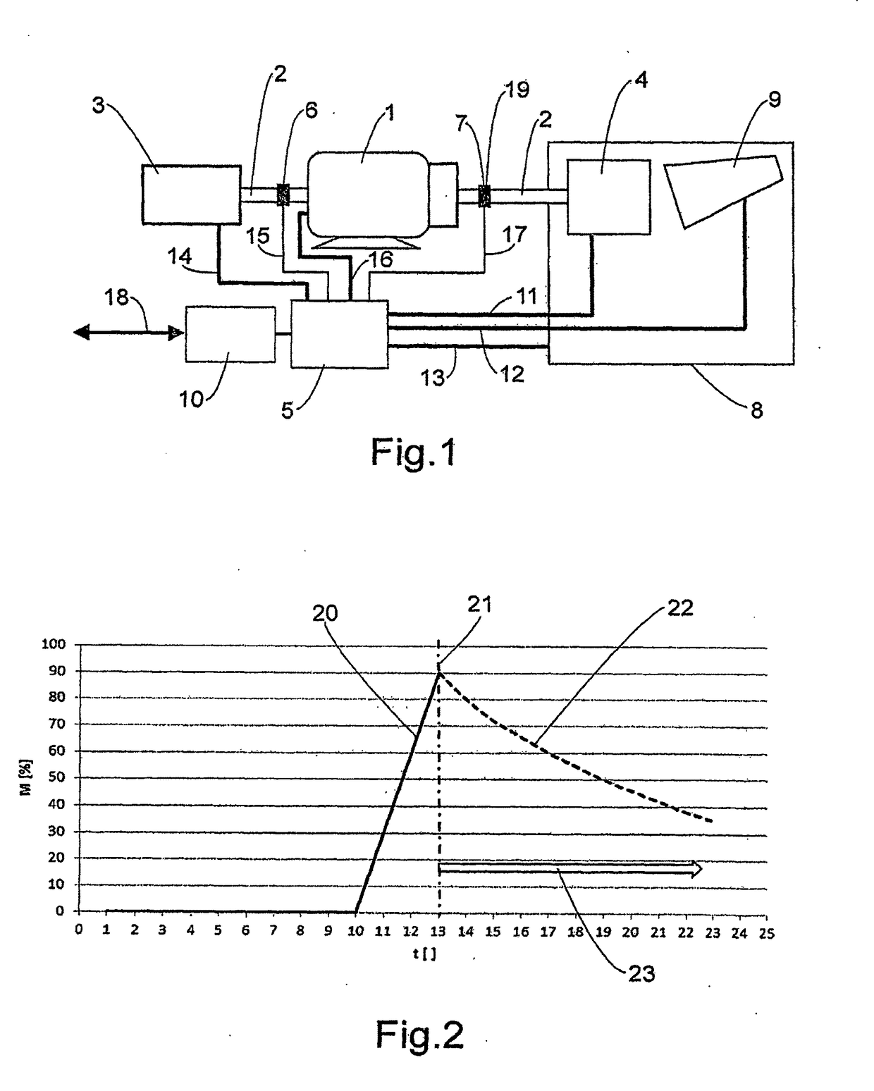
[0030]FIG. 1 shows a schematic representation of a brake test stand according to the invention. The specimen 4 is connected via a torque transmitting device 2 to the drive motor 1. In the representation the torq...


PUM

PropertyMeasurementUnit
torqueaaaaaaaaaa
rotational speedaaaaaaaaaa
torquesaaaaaaaaaa

Abstract

A brake test stand includes at least one driving motor that is coupled, via at least one torque transmitting device to a load generator and at least one brake to be tested, wherein the driving motor provides the energy to be converted by the brake to be tested and the load generator accepts the energy provided by the driving motor at least prior to the brake test.

Description

BACKGROUND OF THE INVENTION[0001]The invention relates to an improved brake test stand. Furthermore, the invention relates to an optimized method for testing a brake. The development times demanded by the market in the automotive sector are becoming increasingly shorter. At the same time the complexity of the assemblies of vehicles is steadily increasing. In the field of brake technology, therefore, test stands have been coming into use for many years with which new developments can be tested and improved before the presence of a complete vehicle. These test stands have the task to provide the most realistic conditions possible for the brake to be tested in order to make safe predictions on the future behavior of the brake in the vehicle.[0002]An essential aspect in the simulation of braking operations on a test stand is the kinetic energy of the vehicle. This energy depends in reality on driving speed but also on vehicle weight and the driving situation, such as cornering or drivin...

Claims


Application Information

Patent Timeline
Patent Type & Authority Applications(United States)
IPC IPC(8): G01L5/28G01M13/02
CPCG01M13/025G01L5/28
Inventor SCHMID, STEFAN
Owner CREDIT SUISSE
Why Eureka
Try Eureka