Check patentability & draft patents in minutes with Patsnap Eureka AI!

Surface acoustic wave sensor coating

a surface acoustic wave and sensor technology, applied in the field of surface acoustic wave (saw) sensors, can solve the problems of chemical adsorption, physical adsorption, grouping into the untreated surface of the saw sensor, etc., and achieve the effect of low energy surfa

Active Publication Date: 2017-11-23
PULMOSTICS LIMTED
View PDF7 Cites 2 Cited by
  • Summary
  • Abstract
  • Description
  • Claims
  • Application Information

AI Technical Summary

Benefits of technology

The present patent is about a surface acoustic wave sensor that overcomes the problem of instrument drift caused by accumulated surface contamination. The sensor has a piezoelectric substrate with a plurality of interdigitated electrodes mounted on its outer surface. An inert coating layer is added to the substrate and electrodes, which helps to prevent the sensor from getting affected by external factors and ensures accurate functioning. The inert coating layer can be made of various compounds like perfluoro-silane, perfluoro-trichloro-silane, etc. The technical effect of this patent is to improve the accuracy and reliability of surface acoustic wave sensors by preventing instrument drift.

Problems solved by technology

First, there is condensation due to the saturation of chemical compounds in the vapor in contact with the SAW sensor.
Second, there is physical adsorption due to weak Van der Waals forces between the substrate surface and the molecules in the vapor.
Third, there is chemical adsorption due to the formation of chemical bonds between the active sites of the substrate / quartz surface and the interdigitate electrodes, and the molecules in the vapor.
The reaction between the SAW surface and the function groups results in the chemical adsorption of the compounds that contain such function groups into untreated surfaces of the SAW sensor.
Over time and multiple analysis cycles, there may be an accumulation of residual compounds that, in turn, affect the oscillation frequency, resulting in instrument drift.
Under some circumstances, it may not be possible to completely reverse the chemical adsorption, even with high temperatures.
Thus, the surface of the SAW sensor may not be entirely clean, or as clean as its initial state, if a high amount of chemical compounds have been chemically adsorbed.
Heavily contaminated sensors require heating for longer durations and at higher temperatures.
To the extent a solvent wash is also insufficient, the SAW sensor may require replacement.

Method used


Image

  • Surface acoustic wave sensor coating
  • Surface acoustic wave sensor coating
  • Surface acoustic wave sensor coating

Examples


Embodiment Construction

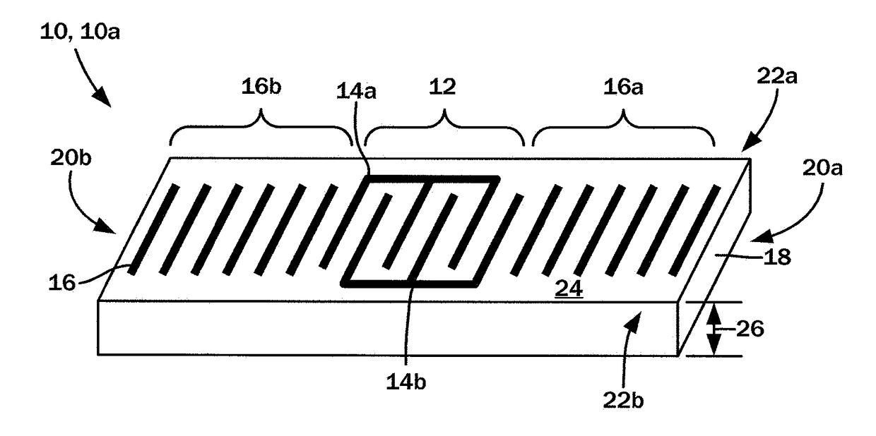
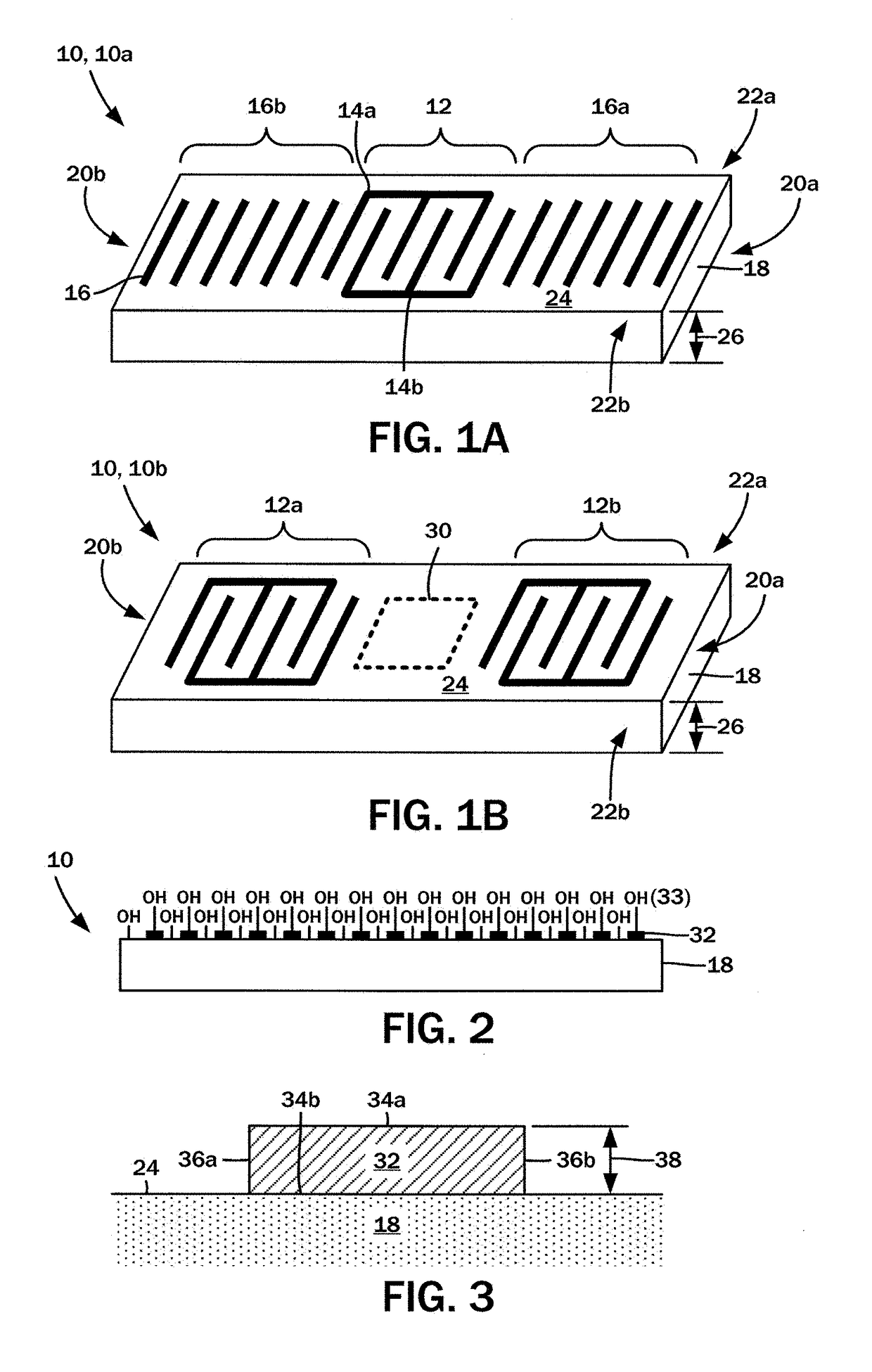
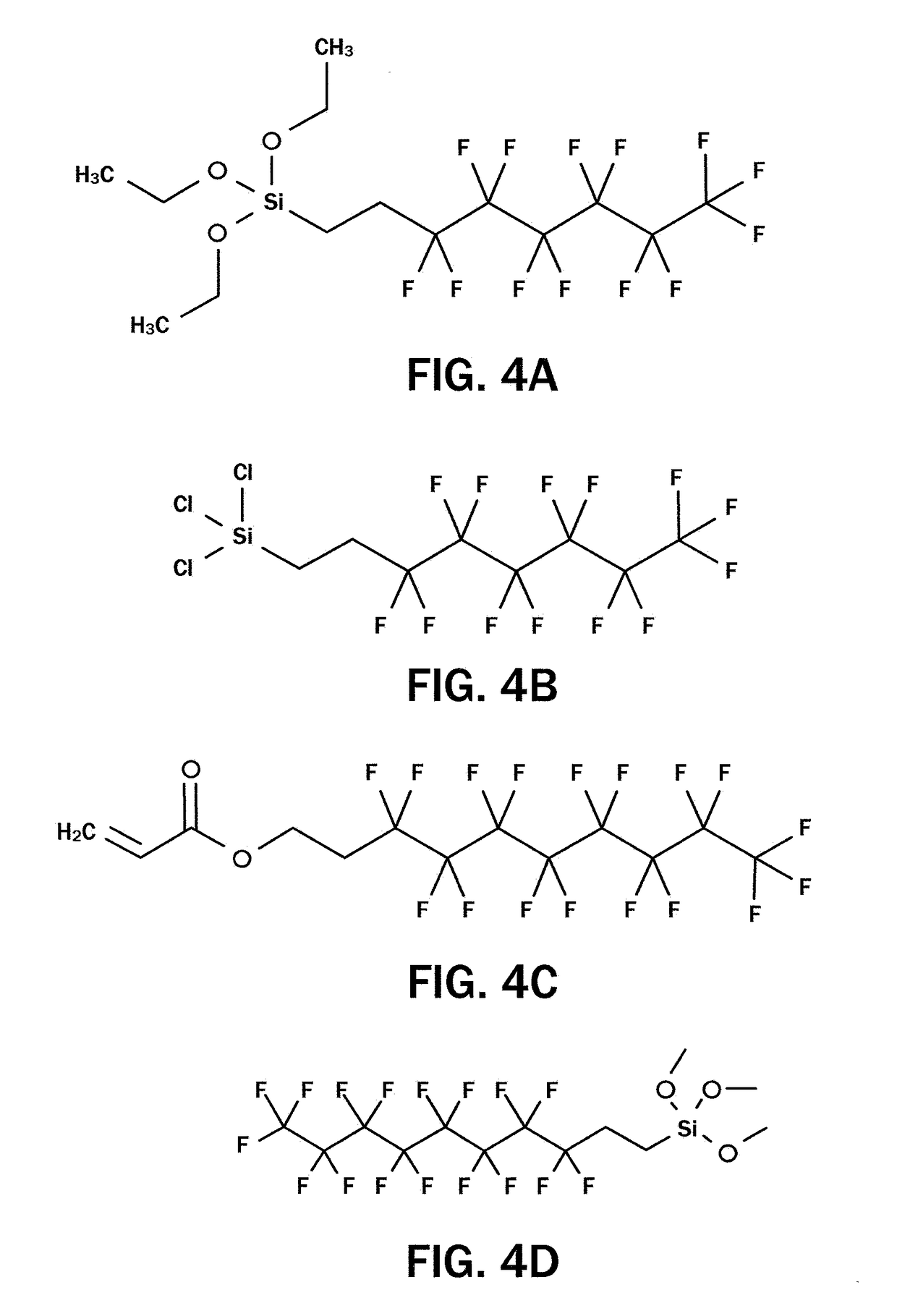
[0026]The present disclosure is directed to various embodiments of a surface acoustic wave (SAW) sensor device utilized in chemical analysis systems. In accordance with these embodiments, these improved sensor devices overcome instrument drift that occurs as a consequence of surface contamination over repeated analysis cycles. As will be described in further detail below, these embodiments may utilize a thin or monolayer of an inert polymer material that coats an entirety of the exposed sensor device. The detailed description set forth below in connection with the appended drawings is intended as a description of the several presently contemplated embodiments of these sensor devices, and is not intended to represent the only form in which the disclosed invention may be developed or utilized. The description sets forth the functions and features in connection with the illustrated embodiments. It is to be understood, however, that the same or equivalent functions may be accomplished b...


PUM


Abstract

A surface acoustic wave sensor in which instrument drift resulting from accumulated surface contamination is minimized. The sensor includes a piezeoelectric substrate defined by an outer surface and a plurality of interdigitated electrodes mounted thereon. The electrodes are defined by one or more exposed portions and an unexposed portion abutting the outer surface of the piezoelectric substrate. An inert coating layer on the outer surface of the piezoelectric substrate and the exposed portions of the electrodes is provided, and can be a perfluoro-silane type compound, a perfluoro-trichloro-silane type compound, a perfluoro-acrylate type compound, polytetrafluoroethylene, or heptadecafluorodecyltrimethoxysilane.

Description

CROSS-REFERENCE TO RELATED APPLICATION(S)[0001]This application relates to and claims the benefit of U.S. Provisional Application No. 62 / 339,359 filed May 20, 2016 and entitled “SURFACE ACOUSTIC WAVE SENSOR COATING,” the entire disclosure of which is hereby wholly incorporated by reference.STATEMENT RE: FEDERALLY SPONSORED RESEARCH / DEVELOPMENT[0002]Not ApplicableBACKGROUND1. Technical Field[0003]The present disclosure relates generally to surface acoustic wave (SAW) sensors employed in the identification of chemicals, and more particularly to coatings applied to SAW sensors to reduce surface contamination due to chemical adsorption.2. Related Art[0004]Surface acoustic wave (SAW) devices are widely used in chemical detection sensor applications. A SAW sensor is generally defined by an input transducer, which converts a known input electronic signal into an acoustic / mechanical wave, and an output transducer that converts that wave back into an electronic signal for further processing....

Claims


Application Information

Patent Timeline
IPC IPC(8): H01L41/113H01L41/053G01N29/24G01N29/02G01N30/76G01N29/32H01L41/18H01L41/047
CPCH01L41/1132H01L41/0533H01L41/0472H01L41/18G01N2291/021G01N29/2443G01N29/32G01N30/76G01N29/022G01N29/036G01N29/2462G01N2291/0255H10N30/302H10N30/85H10N30/872H10N30/883
Inventor SUN, YIN
Owner PULMOSTICS LIMTED
Features
  • R&D
  • Intellectual Property
  • Life Sciences
  • Materials
  • Tech Scout
  • Unparalleled Data Quality
  • Higher Quality Content
  • 60% Fewer Hallucinations
Learn More