Microsurgical bipolar forceps

a bipolar forcep and micro-scopy technology, applied in the field of surgical instruments, can solve the problems that the use of bipolar forceps in neurosurgical procedures presents unique risks to patients

Active Publication Date: 2017-11-30
KOGENT SURGICAL
View PDF2 Cites 4 Cited by
  • Summary
  • Abstract
  • Description
  • Claims
  • Application Information

AI Technical Summary

Benefits of technology

[0004]A microsurgical bipolar forceps is presented. In one or more embodiments, a microsurgical bipolar forceps may comprise an actuation structure, a hypodermic tube, a first electrical conductor, and a second electrical conductor. Illustratively, the actuation structure may comprise an actuation structure distal end, an actuation structure proximal end, and a plurality of actuation limbs. In one or more embodiments, the hypodermic tube may be disposed in the actuation structure. Illustratively, the first electrical conductor may be disposed in the hypodermic tube and the actuation structure wherein the first electrical conductor is electrically connecte

Problems solved by technology

Bipolar forceps are also used in neurosurgical procedures; however, the use of bipolar forceps in neurosurgical procedures presents unique risk

Method used


Image

  • Microsurgical bipolar forceps
  • Microsurgical bipolar forceps
  • Microsurgical bipolar forceps

Examples


Embodiment Construction

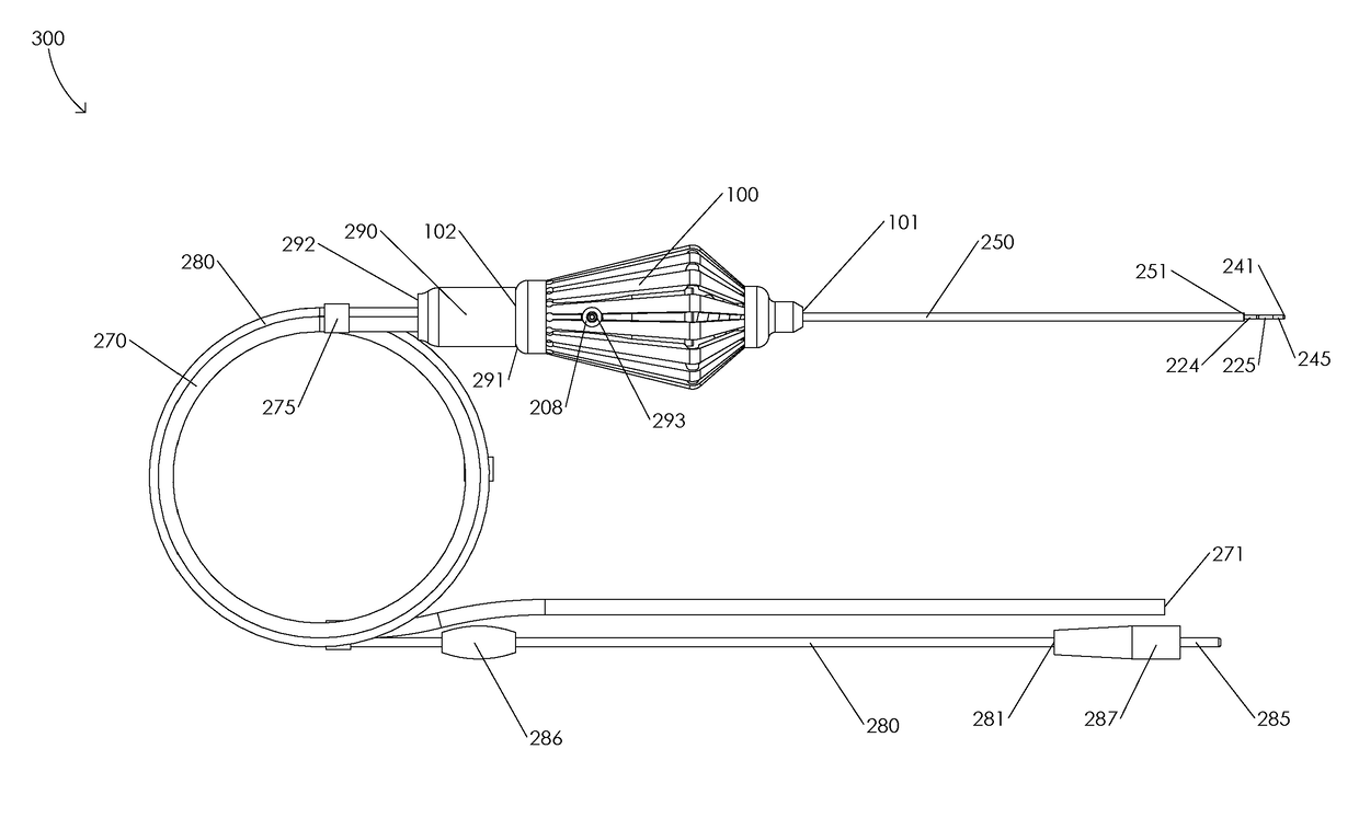
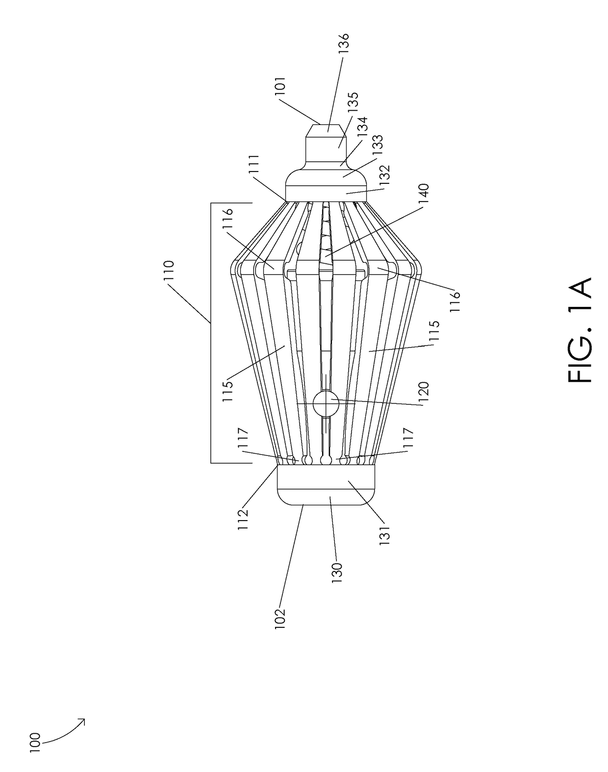
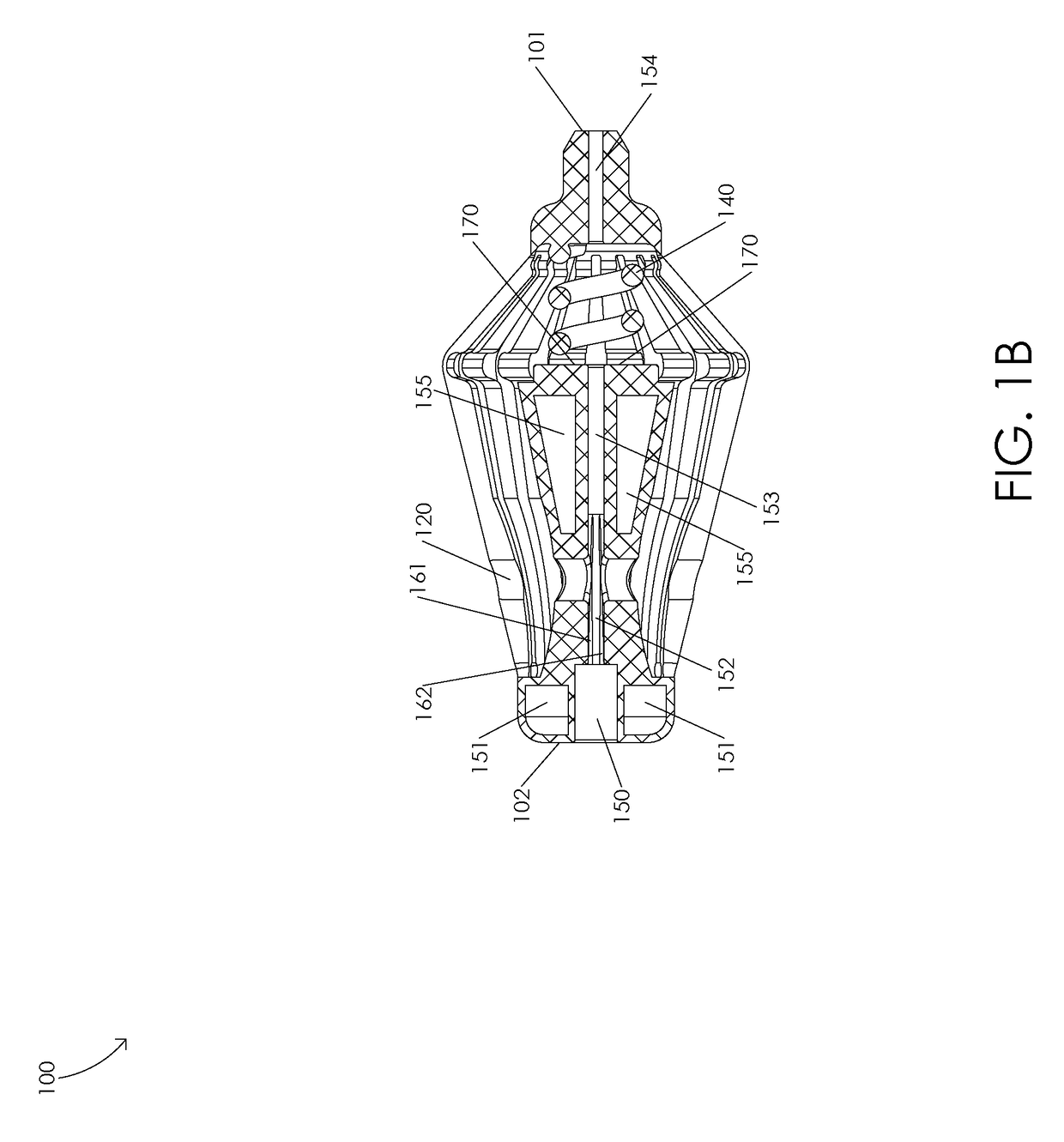
[0010]FIGS. 1A and 1B are schematic diagrams illustrating a handle 100. FIG. 1A is a schematic diagram illustrating a side view of a handle 100. In one or more embodiments, a handle 100 may comprise a handle distal end 101 and a handle proximal end 102. Illustratively, handle 100 may comprise an actuation structure 110 having an actuation structure distal end 111 and an actuation structure proximal end 112. In one or more embodiments, handle 100 may comprise a proximal ring 131 and a distal ring 132, e.g., handle 100 may comprise a proximal ring 131 disposed adjacent to actuation structure proximal end 112 and handle 100 may comprise a distal ring 132 disposed adjacent to actuation structure distal end 111. For example, proximal ring 131 may abut actuation structure proximal end 112 and distal ring 132 may abut actuation structure distal end 111. Illustratively, handle 100 may comprise a handle base 130, e.g., handle 100 may comprise a handle base 130 disposed adjacent to proximal r...


PUM


Abstract

A microsurgical bipolar forceps may include an actuation structure, a hypodermic tube, a first electrical conductor, and a second electrical conductor. The actuation structure may include an actuation structure distal end, an actuation structure proximal end, and a plurality of actuation limbs. The hypodermic tube may be disposed in the actuation structure. The first electrical conductor may be disposed in the hypodermic tube and the actuation structure wherein the first electrical conductor is electrically connected to a bipolar cord. The second electrical conductor may be disposed in the hypodermic tube and the actuation structure wherein the second electrical conductor is electrically connected to the bipolar cord. A compression of the actuation structure may be configured to decrease a distance between a first jaw of the first electrical conductor and a second jaw of the second electrical conductor.

Description

CROSS-REFERENCE TO RELATED APPLICATIONS[0001]This Application claims the benefit of U.S. Provisional Application No. 62 / 343,614, filed May 31, 2016.FIELD OF THE INVENTION[0002]The present disclosure relates to a surgical instrument, and, more particularly, to an electrosurgical instrument.BACKGROUND OF THE INVENTION[0003]A variety of complete surgical procedures and portions of surgical procedures may be performed with bipolar forceps, e.g., bipolar forceps are commonly used in der-matological, gynecological, cardiac, plastic, ocular, spinal, maxillofacial, orthopedic, uro-logical, and general surgical procedures. Bipolar forceps are also used in neurosurgical procedures; however, the use of bipolar forceps in neurosurgical procedures presents unique risks to patients if the surgeon is unable to both visually and tactilely confirm that an electrosurgical procedure is being performed as intended. Accordingly, there is a need for a bipolar forceps that allows a surgeon to both visuall...

Claims


Application Information

Patent Timeline
IPC IPC(8): A61B18/14A61B18/00
CPCA61B18/1445A61B18/1492A61B2018/00184A61B2018/00565A61B2018/00321A61B2018/00351A61B2018/00339A61B2218/002
Inventor SCHELLER, GREGG DHARRIS, JACOB D
Owner KOGENT SURGICAL
Why Eureka
Try Eureka