
Portable roller compactor

a compactor and roller technology, applied in the field of transportable roller compactors, can solve the problems of complex movement kinematics of articulated arms, unfavorable lever ratios, and unfavorable hydraulic drive realization, and achieve the effect of simplifying its construction and movement kinematics, and saving spa

Active Publication Date: 2017-11-30
HUSMANN UMWELT TECHN GMBH
View PDF4 Cites 1 Cited by
  • Summary
  • Abstract
  • Description
  • Claims
  • Application Information

AI Technical Summary

Benefits of technology

The patent describes a compacting machine that can be mounted on a truck or trailer and moved to a container to compress and / or comminute waste. The machine has a roller compactor that can be lowered into the container and move back and forth to compress the waste inside. The roller compactor has a structured surface with teeth or spikes to effectively compound the waste. The machine can also have hydraulic supports that can be extended to support it during transportation. The technical effects of this invention include increased efficiency in waste management and reduction of waste at the source.

Problems solved by technology

The motion kinematics of the articulated arm can, however, be complicated because of the three-part design.
This produces unfavorable lever ratios when pivoting said frame-mounted section of the articulated arm out of its horizontal position.
Due to the large pivot angle, the realization of the pivoting movement by a hydraulic drive is also complex in this construction.
Since the compactor roller has a substantial share of the weight of the roller compactor, this results in an unfavorable weight distribution for transport.

Method used


Image

  • Portable roller compactor
  • Portable roller compactor
  • Portable roller compactor

Examples


Embodiment Construction

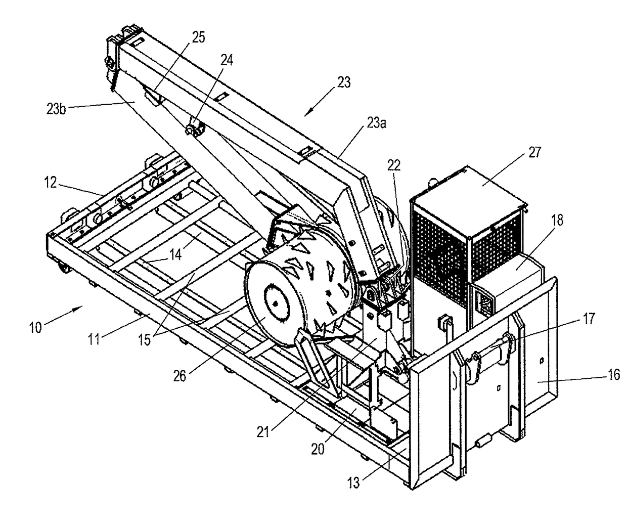
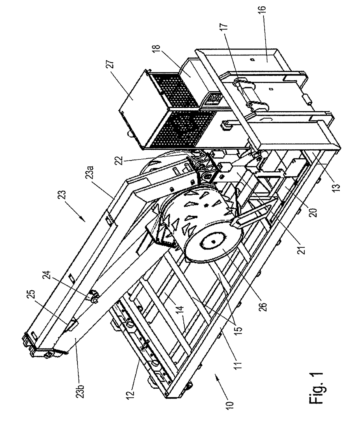
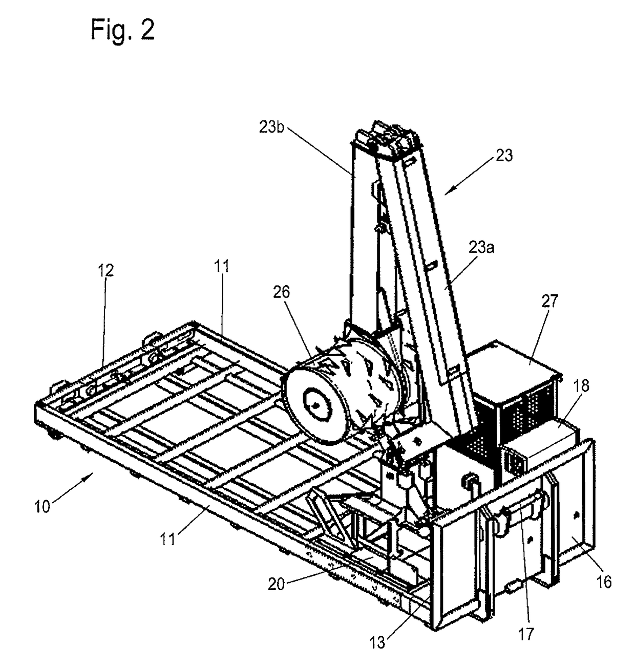
[0018]FIGS. 1 to 5 show an embodiment of a transportable roller compactor according to the application, each in isometric view.

[0019]The drawings show the roller compactor in various operating states from a respective similar viewing direction. Referring to the figures, a transition of the roller compactor is shown from a rest state, in which a transport of the roller compactor can take place, to an operating state in which waste in a container is compressed and / or crushed.

[0020]The roller compactor has a base structure 10, which corresponds in its dimensions, in particular in the dimensions of its base, to a conventional container. The base structure 10 is formed in a frame-like manner with outer longitudinal beams 11, a rear transverse beam 12 and a front transverse beam 13, which is only visible in the drawings. The directional indication at the front or the rear relates to the usual transport direction of the transportable roller compactor, if this is mounted on a truck or a tra...


PUM


Abstract

A portable roller compactor for compacting waste located in a container, which is open on the top, has a frame-like basic structure and an articulated arm, one end of which is supported by the basic structure, and the other, free end of which supports a roller compactor that essentially can be rotated about a horizontal axis of rotation. The articulated arm of the roller compactor is pivotably attached to a sliding carriage, which is mounted on the frame-like base structure and can be moved in a longitudinal direction.

Description

BACKGROUND AND SUMMARY OF THE INVENTION[0001]Exemplary embodiments of the invention relate to a transportable roller compactor for compacting waste located in an open-top container. The roller compactor has a frame-like basic structure, which can be mounted on a loading surface of a truck or trailer. The basic structure carries an articulated arm, which at a free end carries a roller compactor, which is rotatable about a horizontal axis of rotation.[0002]For compacting waste in a container, such a transportable roller compactor is mounted on a loading surface of a truck or trailer and then moved to a front side of an upwardly open container. The compactor roller located at the free end of the articulated arm is lowered into the container. In a pivoting movement of the articulated arm, the compactor roller is moved back and forth in the container, thereby compressing and / or comminuting the waste in the container. The compactor roller is usually rotatable by means of a drive and has a...

Claims


Application Information

Patent Timeline
IPC IPC(8): B30B9/30B30B9/20B30B3/02B30B9/32B30B15/16
CPCB30B9/3082B30B9/3042B30B15/165B30B9/205B30B9/327B30B3/02
Inventor HUSMANN, HEINZ HERMANNMUCHALL, WOLFGANG
Owner HUSMANN UMWELT TECHN GMBH
Learn More