
System and method for sensing high-frequency vibrations on sporting equipment

a high-frequency vibration and sporting equipment technology, applied in the field of high-frequency vibration sensing systems and methods, can solve the problems of high cost, impact robustness concerns, and operational life, and achieve the effects of reducing the number of recharge or battery changes per match, reducing the power and bandwidth requirements of the device, and increasing the system's operational li

Active Publication Date: 2017-11-30
FUTURE TECH IN SPORT
View PDF10 Cites 2 Cited by
  • Summary
  • Abstract
  • Description
  • Claims
  • Application Information

AI Technical Summary

Benefits of technology

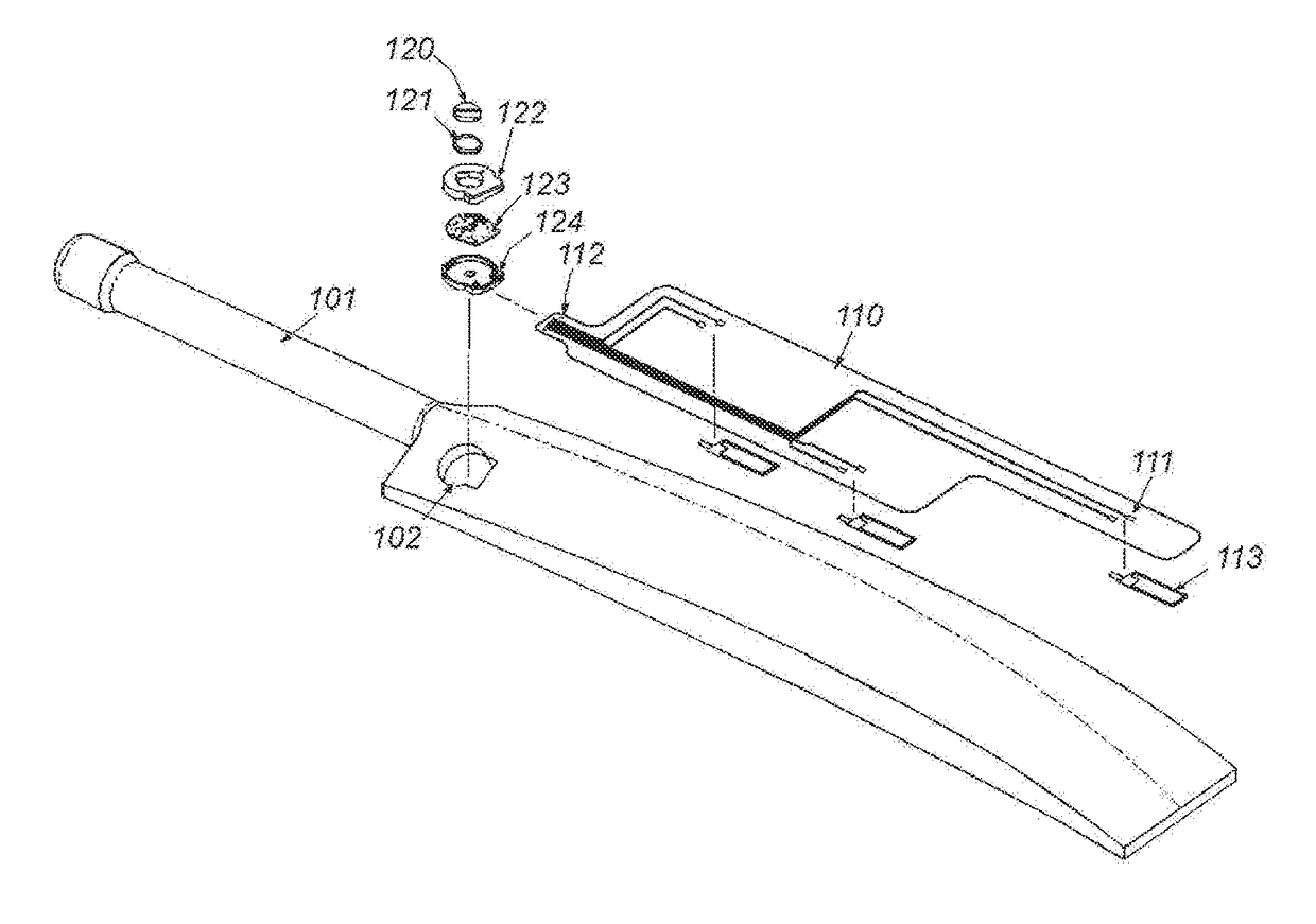
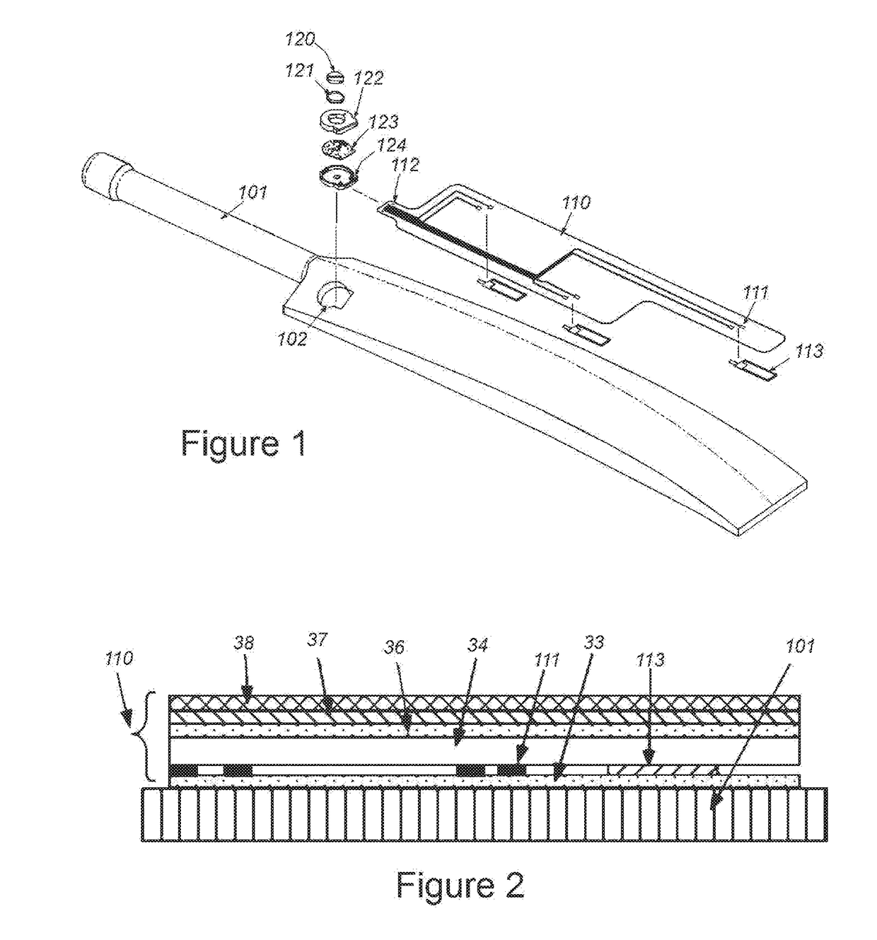
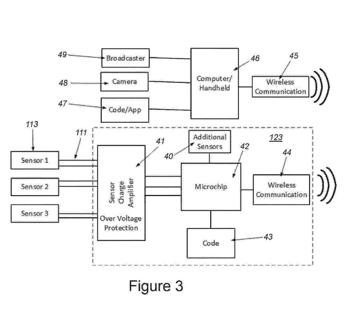
The invention described in this patent integrates highly-sensitive vibration sensors with the art and logos of equipment to make the sensors unobtrusive. The sensors capture low-frequency vibrations and send them to a receiver for analysis. The receiver analyzes the data and picks specific parameters of concern to send via wireless communication to a processor. This architecture reduces the power and bandwidth requirements of the device while maintaining its functionality and the ability to transmit and report parameters and incidents of interest. The sensor arrangement is interconnected to an electronic component, which uses low-power electronics with the ability to capture and analyze specific signals. This system and method for measuring vibrations in sporting equipment can minimize battery power requirements and re-construct data in the receiving end.

Problems solved by technology

The reasons for this include high cost, impact robustness concerns, operational lifetime, intrusiveness to equipment and performance as well as inability to sense vibrations to the level of detail that enables the reduction of performance parameters.

Method used


Image

  • System and method for sensing high-frequency vibrations on sporting equipment
  • System and method for sensing high-frequency vibrations on sporting equipment
  • System and method for sensing high-frequency vibrations on sporting equipment

Examples


Embodiment Construction

[0019]Sensing the vibrations generated in sports equipment has been suggested previously in prior art. The utility of being able to detect if there was contact between the equipment and the ball, the location of the impact as well as the intensity of the impact is well known to those skilled in the art. However the art is salient on methods that can perform this task in a manner such that the market will accept it and hence there are currently no products available to sense the vibrations on sports equipotent.

[0020]To date, methods to detect vibrations in sport equipment have suffered from the following deficiencies:

[0021]Low-frequency sensing. For instance, MEMS accelerometers are only capable of sensing frequencies up to ˜2 kHz where a number of impacts create signals at much higher frequencies.

[0022]Direct impact with the ball. A number of prior art descriptions include placing sensors on the contact surface of the equipment. This increases the probability of damaging the sensors...


PUM


Abstract

This invention provides a highly-sensitive, high-frequency, soft-polymer vibrations sensor that is integrated with the artwork and logo's currently utilized in equipment to make the sensor(s) unobtrusive. Low-power electronics with the ability to capture and analyze specific signals of concern are utilized as to increase the operational lifetime of the system and decrease the number of re-charge or battery changes per match. High-frequency vibration data is captured and stored locally on the equipment where user-defined code can analyze data and pick specific parameters of concern to send via the wireless communications link to a receiver. The receiver is able to capture the data and re-construct events of interest. This architecture reduces the power and bandwidth requirements of the device while maintaining functionality and the ability to transmit and report parameters and incidents of interest.

Description

FIELD OF THE INVENTION[0001]This invention relates to manufacturing and applying high-frequency vibration sensors to sporting equipment, electronics to interpret vibrations, software and methods to identify information regarding vibration and methods to communicate vibration related information to devices physically removed from the equipment.BACKGROUND OF THE INVENTION[0002]Detecting vibrations in sporting equipment is desired as it can provide a wealth of information regarding the state of play. For instance, in tennis and volleyball, rulings are made based on if the net was touched or not; in cricket and baseball, batsmen can be ruled out if they touched the ball with their bats etc.[0003]Furthermore, as sports coaching becomes more technologically advanced, the ability to locate the impact of a ball on a bat is desirable in order to instruct students how to improve their game.[0004]Televised sports generate substantial revenues for broadcasting companies. These companies employ ...

Claims


Application Information

Patent Timeline
IPC IPC(8): G01H11/08H04N5/225H04N5/04
CPCG01H11/08H04N5/04H04N5/2257H04N23/57
Inventor PRETORIUS, JACOB VAN REENEN
Owner FUTURE TECH IN SPORT
Learn More