Current sensor

a current sensor and sensor technology, applied in the field of current sensors, can solve the problems of reducing the sectional area of the plate-like conductor, reducing the size of the entire current sensor, and large measurement errors, so as to increase the ratio of the second conductor to the conductor, reduce the length of the first conductor, and reduce the effect of measurement error

Active Publication Date: 2017-11-30
ALPS ALPINE CO LTD
View PDF3 Cites 15 Cited by
  • Summary
  • Abstract
  • Description
  • Claims
  • Application Information

AI Technical Summary

Benefits of technology

[0025]Therefore, even if the length of the first conductor part in the length direction is relatively short, an even magnetic field can be easily generated in the magnetic sensor by a current flowing in the first conductor part. This enables positional precision required in the placement of the magnetic sensor to be relaxed. As the length of the first conductor part is shortened, the ratio of the second conductor part to the conductor is increased. This can further reduce the resistance loss in the conductor.
[0026]The present invention can suppress measurement error due to the influence of a current flowing in a conductor adjacent to another conductor in which a current under measurement flows and can also widen the frequency band in which a current can be measured with small measurement error.

Problems solved by technology

The above problem with frequency characteristics also arises when, for example, a multi-channel current sensor is used to detect each of currents flowing in a plurality of adjacent plate-like conductors by using a magnetic sensor.
This causes another problem that measurement error becomes large.
In this method, however, the size of the entire current sensor is enlarged.
In this method, however, the cross-sectional area of the plate-like conductor is reduced and a resistance loss is thereby increased, limiting the maximum current rating.

Method used


Image

  • Current sensor
  • Current sensor
  • Current sensor

Examples


Embodiment Construction

[0033]A current sensor according to an embodiment of the present invention will be described with reference to the drawings.

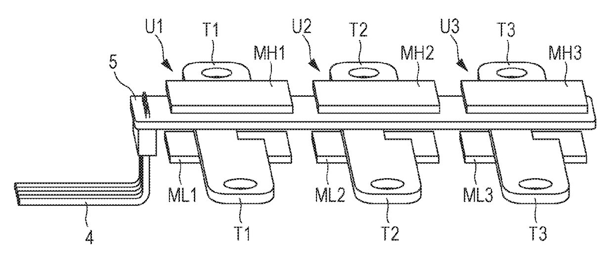
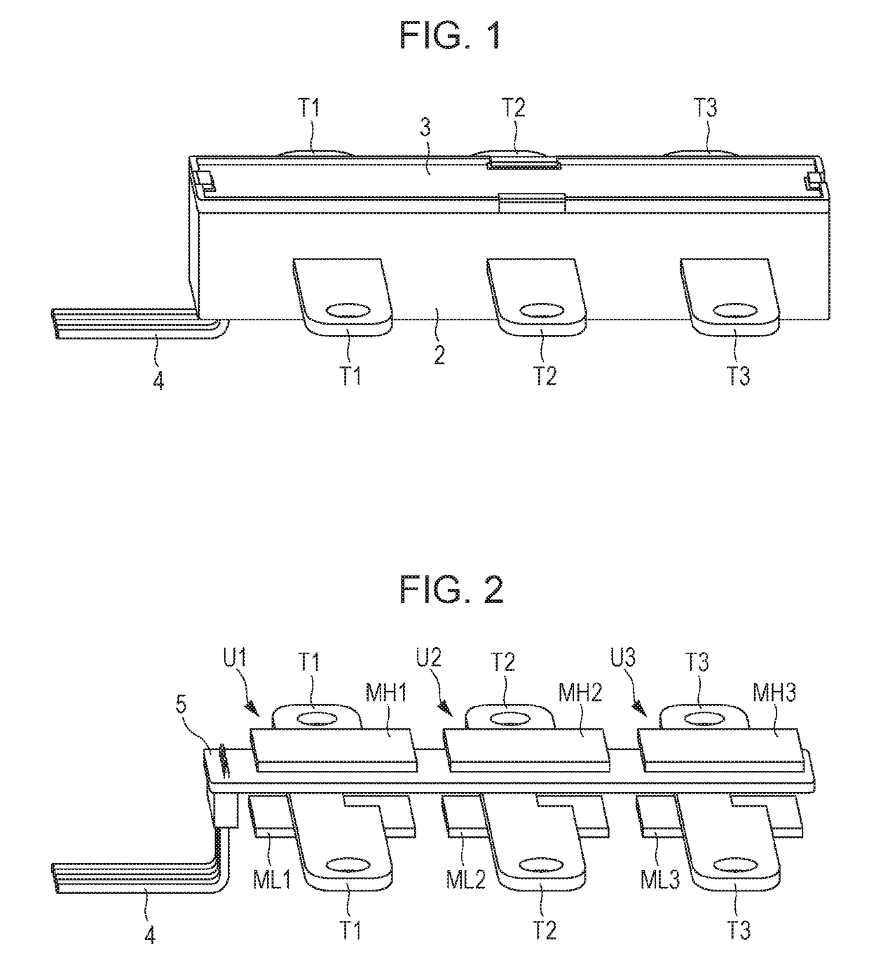
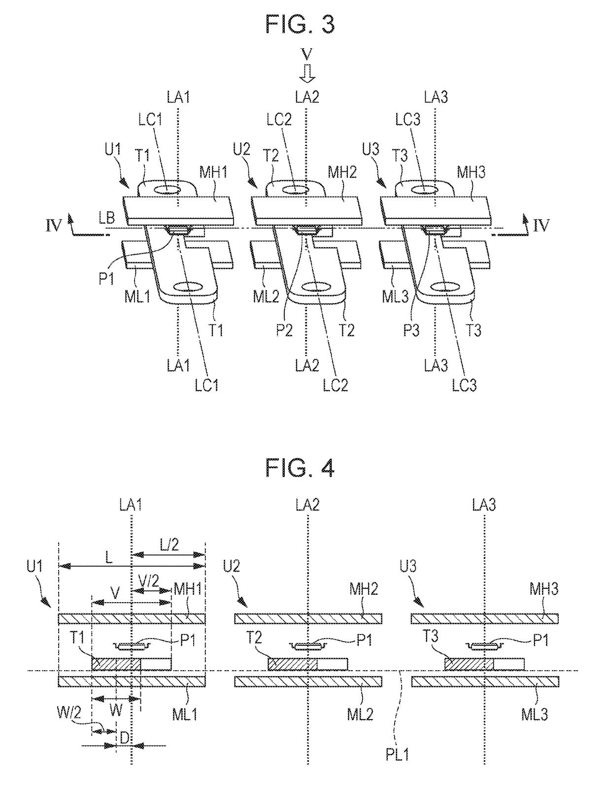
[0034]FIG. 1 illustrates an example of the outside shape of the current sensor according to this embodiment. FIG. 2 illustrates an example of the internal structure of the current sensor illustrated in FIG. 1 with the cases 2 and 3 omitted. FIG. 3 illustrates the internal structure of the current sensor illustrated in FIG. 1 with the circuit board 5 and terminal 4 omitted. FIG. 4 is a cross-sectional view of the internal structure of the current sensor illustrated in FIG. 3, as taken along line IV-IV. FIG. 5 illustrates the internal structure of the current sensor illustrated in FIG. 3, as viewed in the direction indicated by arrow V; the magnetic shields (MH1 to MH3) that would otherwise appear in front as viewed in that direction are omitted.

[0035]The current sensor in the examples in the drawings referenced above is a three-channel current sensor that can in...


PUM


Abstract

Each of three magnetic sensors is positioned on a first virtual line that passes the centers of two magnetic shields in the width direction and is perpendicular to a virtual plane, so a value detected by the magnetic sensor is less likely to be influenced by an external magnetic field. The first virtual line and the center of a conductor intersecting the first virtual line are separated from each other by a certain distance. Therefore, even if a distance from the center of the conductor in the width direction to the magnetic sensor is short, it is possible to improve, on a high-frequency side, frequency characteristics in the detection sensitivity of the magnetic sensor for the frequency of the current under measurement.

Description

CLAIM OF PRIORITY[0001]This application is a Continuation of International Application No. PCT / JP2016 / 057605 filed on Mar. 10, 2016, which claims benefit of Japanese Patent Application No. 2015-053847 filed on Mar. 17, 2015. The entire contents of each application noted above are hereby incorporated by reference.BACKGROUND OF THE INVENTION1. Field of the Invention[0002]The present invention relates to a current sensor that uses magnetic sensors to detect currents, and more particularly to a current sensor that detects currents flowing in a plurality of adjacent conductors.2. Description of the Related Art[0003]A generally known current sensor is structured so that a magnetic sensor (such as a magnetoresistance effect element) that can be mounted on a circuit board as a chip part is placed in the vicinity of a conductor in which a current to be detected flows and the intensity of a magnetic field detected by the magnetic sensor is output as the detected value of the current.[0004]Whe...

Claims


Application Information

Patent Timeline
Patent Type & Authority Applications(United States)
IPC IPC(8): G01R15/14
CPCG01R15/148G01R15/205
Inventor ABE, MINORU
Owner ALPS ALPINE CO LTD
Why Eureka
Try Eureka