Printing apparatus and printing control device

a printing control device and printing control technology, applied in the direction of printing, instruments, visual presentation, etc., can solve the problems of damage to any of the printing control device mechanisms, the printer cannot operate normally,

Active Publication Date: 2017-11-30
OKI ELECTRIC IND CO LTD
View PDF3 Cites 9 Cited by
  • Summary
  • Abstract
  • Description
  • Claims
  • Application Information

AI Technical Summary

Benefits of technology

[0007]According to the aspects of the invention, it is possible to avoid occurrence of an error state that disables normal operation of the printing

Problems solved by technology

Small shreds of the adhesive labels may be formed between the actual cut position and the half-cut line, and the small shred may possibly adhere (by winding around or getting stuck, for example) to th

Method used


Image

  • Printing apparatus and printing control device
  • Printing apparatus and printing control device
  • Printing apparatus and printing control device

Examples


first embodiment

> First Embodiment

> Configuration of First Embodiment

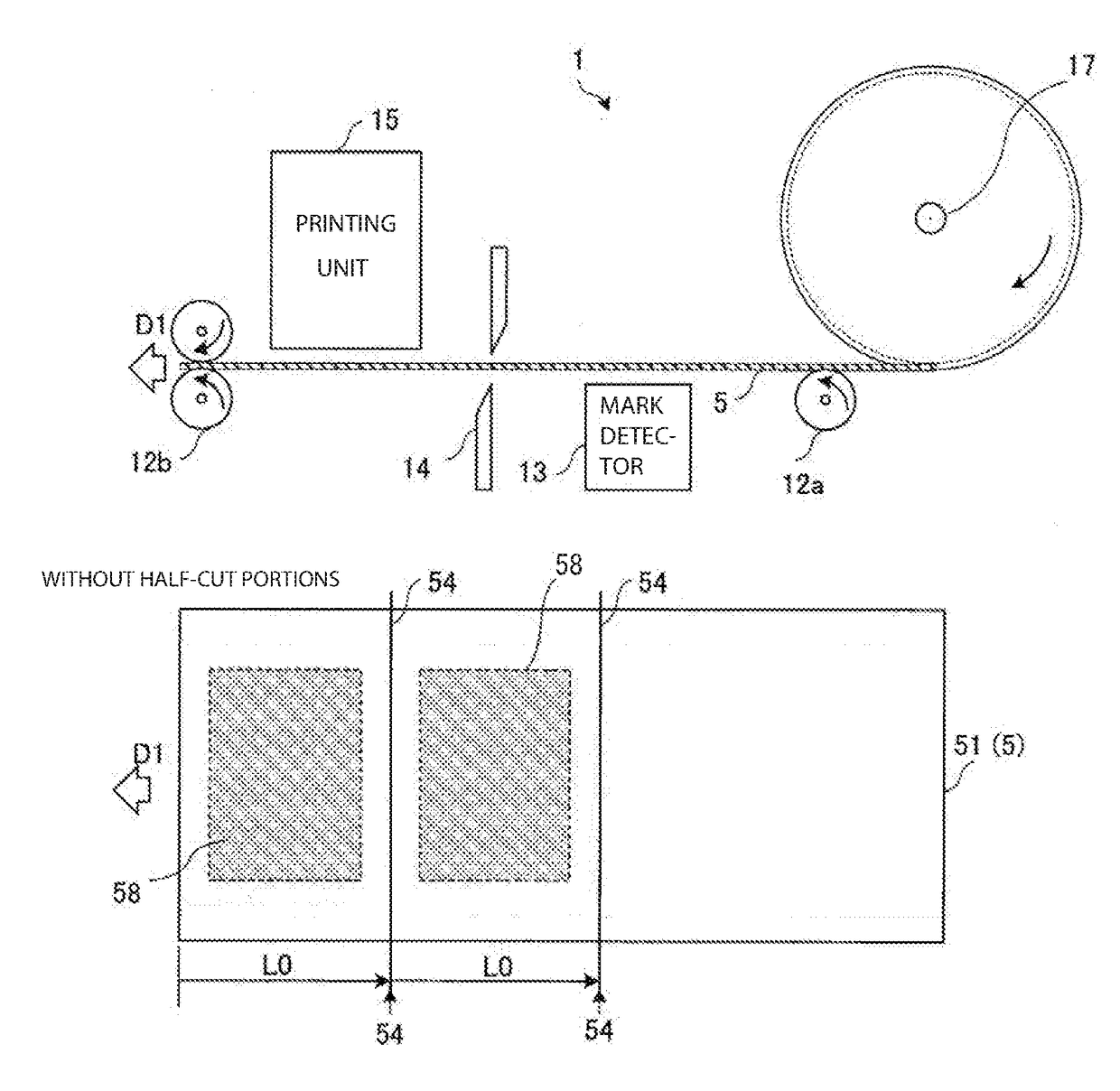
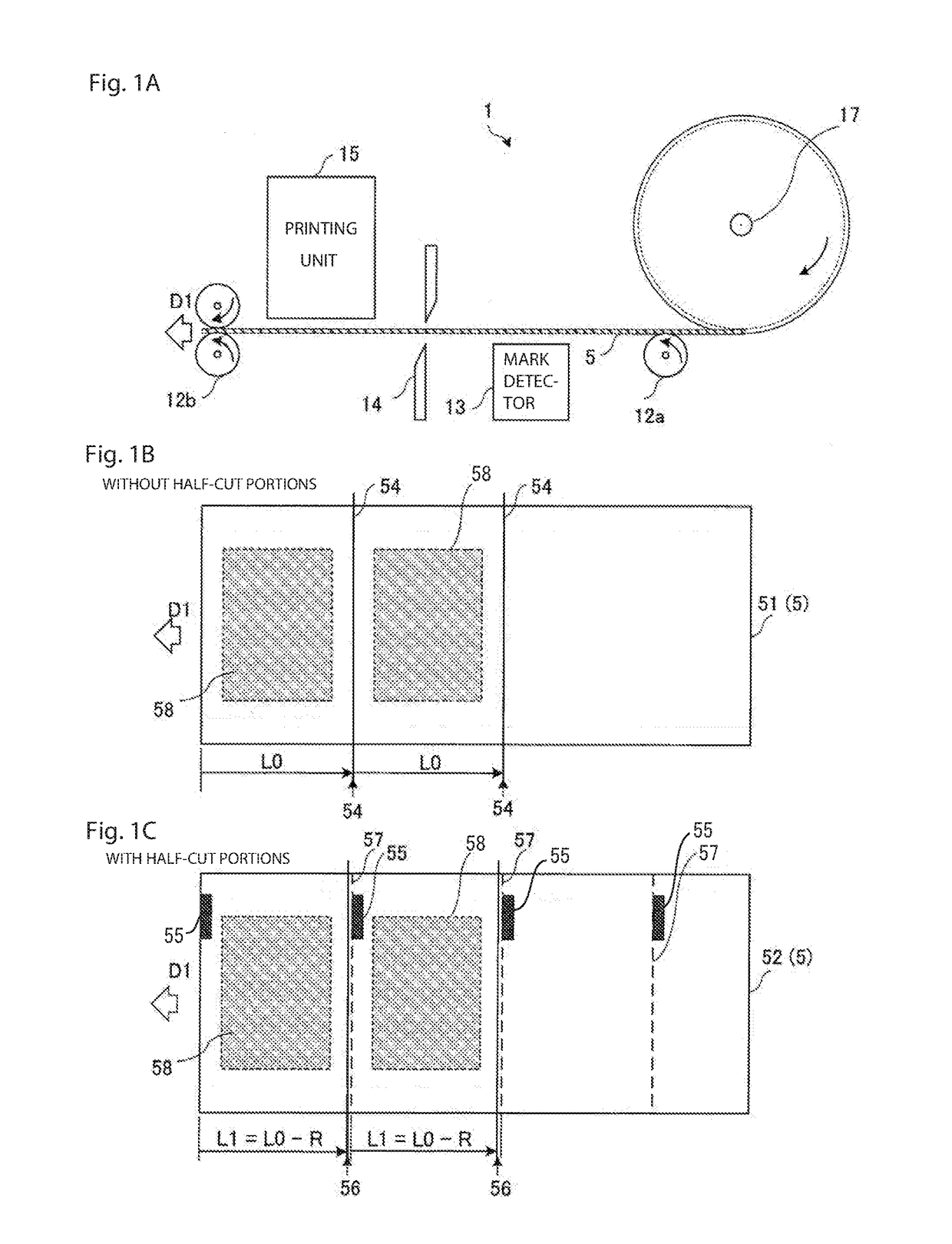
[0021]FIG. 1A is a schematic diagram illustrating a structure of printer 1 according to one or more embodiment, FIG. 1B is a plan view schematically illustrating a back side of label paper sheet 51 without half-cut lines (or separation inducing lines) serving as record medium 5, and FIG. 1C is a plan view schematically illustrating a back side of label paper sheet 52 with half-cut lines (or separation inducing lines) serving as record medium 5. In general, each of label paper sheets 51 and 52 is formed from a backing sheet, and an adhesive label sheet provided with an adhesive surface and laminated on the backing sheet. The label paper sheet 52 with half-cut lines includes the adhesive label sheet that is divided into plural adhesive labels by cuts (so-called half cut lines) therebetween. Note that record medium 5 is not limited only to such a label paper sheet. In addition, record medium 5 does not always have to be rolled up. Fu...

second embodiment

> Second Embodiment

> Configuration of Second Embodiment

[0039]In the first embodiment, a check box for setting the “half-cut medium” is not provided on the screen for designating the sheet type displayed on display 33 of information processing device 3. On the other hand, in a second embodiment, the cut position is changed when check box 33b for setting the “half-cut medium” is selected on the screen for designating the sheet type displayed on display 33 of information processing device 4.

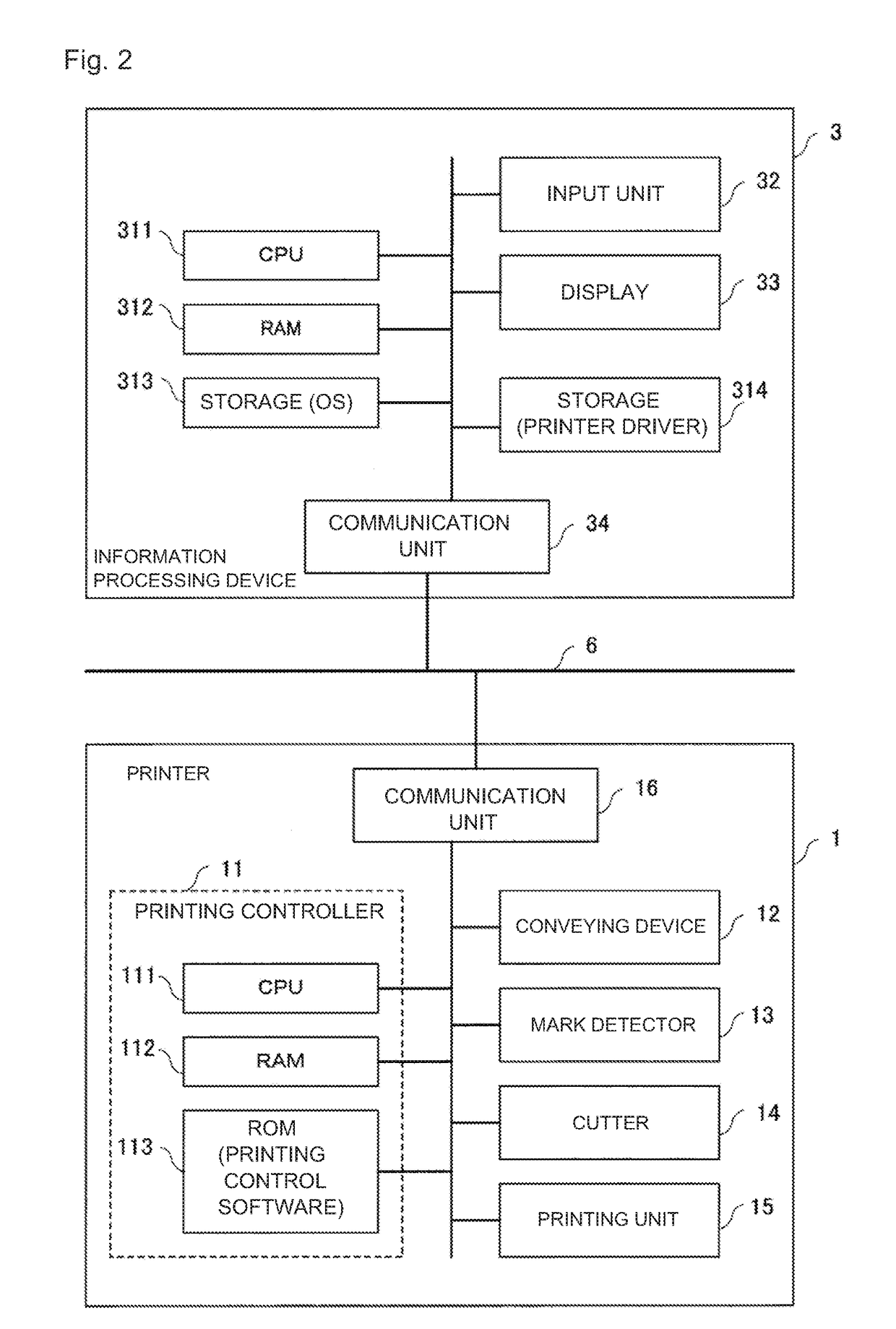
[0040]FIG. 7 is a block diagram schematically illustrating a hardware configuration of a printer system according to the second embodiment. In FIG. 7, constituents which are identical or corresponding to the constituents illustrated in FIG. 2 (the first embodiment) are denoted by the same reference numerals as those indicated in FIG. 2. The printer system according to the second embodiment is different from the printer system according to the first embodiment in terms of a printer driver stored in s...


PUM


Abstract

A printing apparatus according to an embodiment includes: a conveying device which conveys a record medium in a conveyance direction; a cutter which cuts out the record medium; a printing unit which prints an image on the record medium; a mark detector which detects a reference mark indicating a page start position of the record medium; a receiver which receives record medium type information; and a controller which, based on a content of the record medium type information, switches a cut position to be cut with the cutter between a first position being a position upstream in the conveyance direction by a predetermined one-page length from the page start position and a second position being a position shifted in the conveyance direction by a prescribed length from the first position.

Description

CROSS REFERENCE TO RELATED APPLICATIONS[0001]This application claims priority based on 35 USC 119 from prior Japanese Patent Application No. 2016-108806 filed on May 31, 2016, entitled “PRINTING APPARATUS AND PRINTING CONTROL DEVICE”, the entire contents of which are incorporated herein by reference.BACKGROUND1. Field[0002]This disclosure relates to a printing apparatus (a printer) which prints an image on a record medium, and to a printing control device (a printer control device) which controls the printing apparatus.2. Description of Related Art[0003]There has been proposed a printer which includes: a sensor that detects marks provided at regular intervals on rolled paper as a record medium; a printing unit that starts printing based on the position of a detected mark; and a cutter mechanism (a cutter) that cuts out the rolled paper based on the position of the mark detected next (for example, see Patent Document 1: Japanese Patent Application Publication No. 2012-228839).SUMMARY...

Claims


Application Information

Patent Timeline
IPC IPC(8): G06K15/12B41J5/32G06K17/00B41J5/31B41J5/46G06K15/02
CPCG06K15/128G06K17/0012B41J5/32G06K17/0003B41J5/46G06K15/02B41J5/31B41J11/663B41J11/703G06K15/024G06K15/1868
Inventor SHIRASAKA, MITSUYOSHI
Owner OKI ELECTRIC IND CO LTD
Why Eureka
Try Eureka