Paraxial revision rod-to-rod connector

a technology of rod-to-rod connector and paraxial fusion, which is applied in the direction of internal osteosynthesis, internal osteosynthesis, osteosynthesis devices, etc., can solve the problems of difficult removal of previously implanted rods, time-consuming procedure, and inability to fuse additional vertebra

a technology of rod-to-rod connector and paraxial fusion, which is applied in the direction of internal osteosynthesis, internal osteosynthesis, osteosynthesis devices, etc., can solve the problems of difficult removal of previously implanted rods, time-consuming procedure, and inability to fuse additional vertebra

US20170348026A1Active Publication Date: 2017-12-07STRYKER EURO OPERATIONS HLDG LLC

Image

  • Paraxial revision rod-to-rod connector
  • Paraxial revision rod-to-rod connector
  • Paraxial revision rod-to-rod connector

Examples


Embodiment Construction

[0029]In order to develop an appreciation of the principles of the invention, several embodiments as presented in FIGS. 1-10 will be described in the following written specification. The scope of the invention is not intended, however, to be restricted to the embodiments described below. It is also understood that the present invention includes alterations and modifications to the illustrated embodiments and includes further applications of the principles of the invention as would normally occur to one skilled in the art to which this invention belongs.

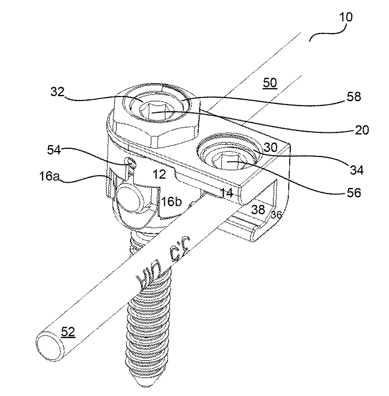
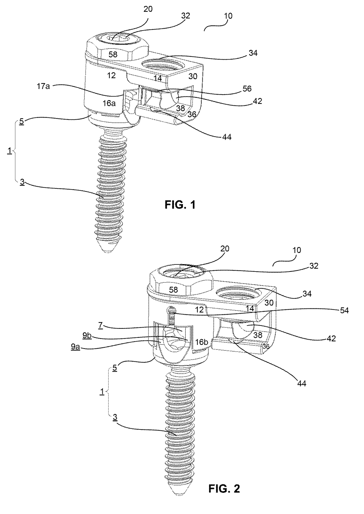
[0030]As is shown in FIGS. 1 and 2, an orthopedic rod-to-rod connector 10 is disclosed as including two connector portions 12 and 14. The connector portions are rotatably coupled to each other, in the manner discussed more fully below. Connector portion 12 is designed to cooperate with a pedicle screw 1 having a first spinal rod 50 disposed therein, and connector portion 14 is designed to receive a second spinal rod 52. In many cases,...


PUM


Abstract

Disclosed herein are an orthopedic rod-to-rod connector and rod-to-rod connector assemblies for spinal fusion surgery. The rod-to-rod connector may include a first connector portion and a second connector portion. The first connector portion may have a first aperture configured to receive at least a portion of a bone-engaging screw and a first spinal rod. The second connector portion may be rotatably connected with the first connector portion and may include a second aperture to receive a second spinal rod. The second connector portion may be L-shaped and may include a set screw to control rotation of the first connector portion with respect to the second connector portion.

Description

CROSS-REFERENCE TO RELATED APPLICATION[0001]The present application claims the benefit of the filling date of U.S. Provisional Patent Application No. 62 / 346,078, filed Jun. 6, 2016, the disclosure of which is hereby incorporated herein by reference.BACKGROUND OF THE INVENTION[0002]The present invention relates to spinal fusion surgery involving the use of pedicle (or lateral mass screws in the case of the cervical spine), and in particular, to devices and methods for adding additional spinal rod segments to already placed pedicle or lateral mass screw and rod constructs.[0003]The spinal column is a complex system of bones and connective tissues that provides support for the body and protects the spinal cord. The system includes a number of vertebrae arranged to form a strong pillar-like structure, with each vertebral body cushioned by intervertebral discs placed between adjacent bodies. These discs are formed from a fibro-cartilage material and not only protect the spinal column fro...

Claims


Application Information

Patent Timeline
07 Dec 2017
Publication
US20170348026A1
IPC
A61B17/70; A61B17/64
CPC
A61B17/7049; A61B17/705; A61B17/645; A61B17/7041; A61B17/7052; A61B17/7032; A61B17/7043
Inventors
STEIN, JOSHUA; BANDEIRA, CARLA