Alarm valve station of a fire extinguishing system, in particular a sprinkler or spray water extinguishing system, and fire extinguishing system

a technology of fire extinguishing system and alarm valve, which is applied in the direction of valve housing, functional valve type, transportation and packaging, etc., can solve the problems of high cost and complication, possible leakage, and increased inspection complication and expenditure,

Active Publication Date: 2017-12-07
MINIMAX LIMITED
View PDF11 Cites 7 Cited by
  • Summary
  • Abstract
  • Description
  • Claims
  • Application Information

AI Technical Summary

Benefits of technology

[0009]For reading off the display values of the sensors and / or checking whether actuators of a fire extinguishing system are actuated as is desired the fire signalling and / or extinguishing control centre is usually read out or control signals are passed by way of that centre to the actuators, which are connected in signal-conducting relationship to the corresponding sensors and / or actuators. The fire signalling and / or extinguishing control centre is however usually disposed in a separate room, particularly in the case of complex fire extinguishing systems. The maintenance staff, for example sprinkler maintenance, fitters or service operatives cannot therefore perform checking of the sensors and / or triggering of the control signal to the actuators directly at the alarm valve of a fire extinguishing system. That considerably increases the complication and expenditure involved in inspection, in particular with large systems.
[0068]In a further preferred development of the disclosure the housing of the fire extinguishing system valve has a housing cover, preferably a hand hole cover, wherein in particular one, more or all of the following elements are integrated in the housing cover: the pressure sensor, the data interface, the data memory and the electronic evaluation unit. In that way it is possible to reduce the component diversity in a series of fire extinguishing system valves without having to compromise function diversity. It is possible to produce a universal housing body which has suitable openings for all functionalities afforded and housing covers of differing configuration. By allocating the respective housing cover with its functionalities integrated therein with the universal housing body the respectively different functions of the fire extinguishing system valve are then brought together. That modular system according to the disclosure further makes it possible subsequently, in relation to existing fire extinguishing systems, to add additional functions or to remove functions which are not required in practice, by changing the housing cover. All that is achieved without removing fitments on the existing fire extinguishing system or having to subsequently install same, which would respectively involve a high level of cost and complication and possible leaks. The housing cover, for example in the embodiment in the form of a hand hole cover, preferably has known and tried-and-tested sealing mechanisms which allow reliable use.

Problems solved by technology

The maintenance staff, for example sprinkler maintenance, fitters or service operatives cannot therefore perform checking of the sensors and / or triggering of the control signal to the actuators directly at the alarm valve of a fire extinguishing system.
That considerably increases the complication and expenditure involved in inspection, in particular with large systems.
All that is achieved without removing fitments on the existing fire extinguishing system or having to subsequently install same, which would respectively involve a high level of cost and complication and possible leaks.
They can prevent release by means of the locking action, but do not actively restore the locking effect after release has occurred.
The fact that this option of remote control is afforded means that the time and personnel involvement necessary for testing the operational readiness of the fire extinguishing system thus falls considerably.

Method used


Image

  • Alarm valve station of a fire extinguishing system, in particular a sprinkler or spray water extinguishing system, and fire extinguishing system
  • Alarm valve station of a fire extinguishing system, in particular a sprinkler or spray water extinguishing system, and fire extinguishing system
  • Alarm valve station of a fire extinguishing system, in particular a sprinkler or spray water extinguishing system, and fire extinguishing system

Examples


Embodiment Construction

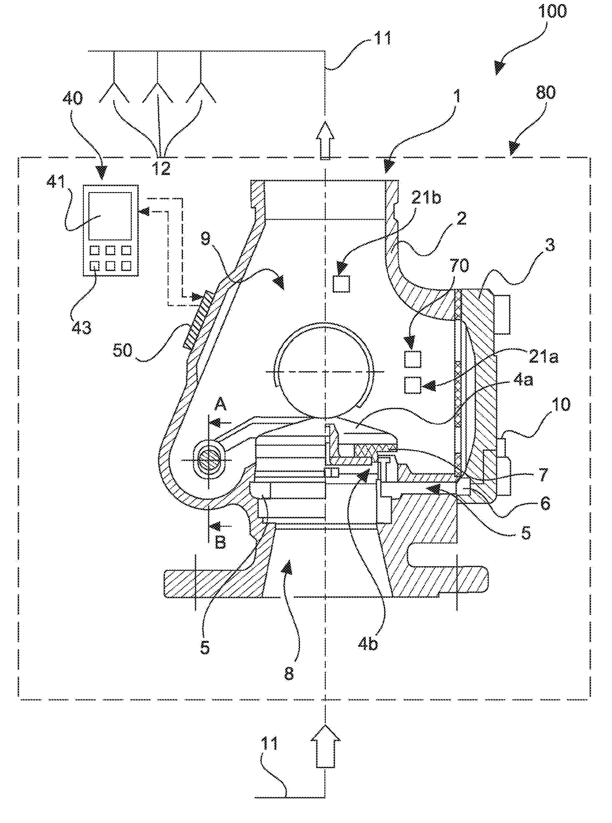
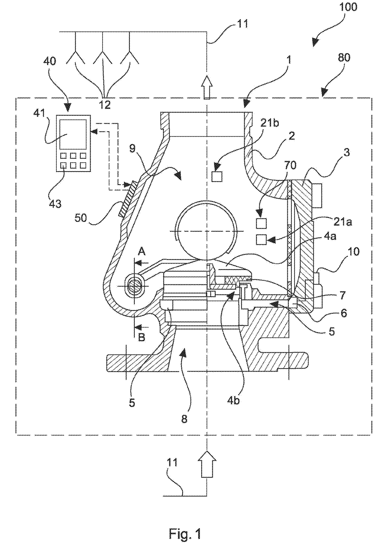
[0104]The fire extinguishing system 100 in FIG. 1 is in the form of a sprinkler extinguishing system and has a fire extinguishing system valve 1, a plurality of fluid lines 11 and a display unit 40. The fire extinguishing system valve 1 and the display unit 40 are component parts of an alarm valve station 80.

[0105]The fire extinguishing system valve 1 for blocking and opening the fluid lines 11 includes a housing 2, 3 having a fluid inlet chamber 8, a fluid outlet chamber 9 and a closing body 4a reciprocable between a blocking state and a release state. Reciprocal includes here not only a translatory movement but also rotatory and other forms of movement. The fluid inlet chamber 8 and the fluid outlet chamber 9 are separated from each other in the blocking state and are in fluid-communicating relationship with each other in the release state. Integrated into the housing 2 is the alarm passage 5 which is in communication with the valve seat 4b and in which a pressure sensor 6 is oper...


PUM


Abstract

An alarm valve station includes a fire extinguishing system valve (1) having a housing (2, 3) which has a fluid inlet chamber (8), a fluid outlet chamber (9) and a closing body (4a) reciprocable between a blocking state and a release state, wherein the fluid inlet chamber (8) and the fluid outlet chamber (9) are separated from each other in the blocking state and communicate with each other in fluid-conducting relationship in the release state, one or more sensors, and an electronic evaluation unit (50) which is integrated in the housing (2, 3), arranged externally on the housing or arranged in the proximity of the fire extinguishing system valve (1), wherein the evaluation unit (50) is connected in signal-conducting relationship to the sensor or sensors for receiving data, is adapted for data processing into: state information and / or operating instructions and is adapted to transmit the state information and / or operating instructions to a display unit (40).

Description

CROSS-REFERENCE TO RELATED APPLICATIONS[0001]This application is a National Stage of International Application No. PCT / EP2015 / 080578, filed Dec. 18, 2015 (now WO 2016 / 097335A1, published Jun. 23, 2016), which is based on German Application No. 102014226639.4, filed Dec. 19, 2014. The entire disclosures of each of the above applications are incorporated herein by reference.FIELD[0002]The disclosure concerns an alarm valve station of a fire extinguishing system, in particular a sprinkler or spray water extinguishing system, comprising a fire extinguishing system valve comprising a housing which has a fluid inlet chamber, a fluid outlet chamber and a closing body reciprocable between a blocking state and a release state, wherein the fluid inlet chamber and the fluid outlet chamber are separated from each other in the blocking state and communicate with each other in fluid-conducting relationship in the release state. The disclosure further concerns such a fire extinguishing system havi...

Claims


Application Information

Patent Timeline
Patent Type & Authority Applications(United States)
IPC IPC(8): A62C37/50A62C35/68F16K37/00
CPCA62C37/50F16K37/0041F16K37/005A62C35/68A62C37/44F16K1/20F16K27/0227G08B17/04A62C35/60A62C35/605F16K15/033Y10T137/8326F16K27/12
Inventor POHL, MATTHIASSTACHOWITZ, FRANKKEMPF, PETERKUNERT, GEORG
Owner MINIMAX LIMITED
Why Eureka
Try Eureka