Hydraulic shock absorber

a technology of shock absorber and shock absorber, which is applied in the direction of shock absorbers, steering devices, cycle equipments, etc., can solve the problems of increasing the rate of coil springs, affecting ride comfort, and requiring a relatively large preset, so as to increase the comfort of the vehicle occupant, reduce weight, and increase the weight and complication of the structure

Inactive Publication Date: 2012-09-04
HONDA MOTOR CO LTD
View PDF2 Cites 7 Cited by
  • Summary
  • Abstract
  • Description
  • Claims
  • Application Information

AI Technical Summary

Benefits of technology

[0020]According the configuration of the first aspect and feature of the present invention, he pressure side damping force generator has a bladder pressurization type structure such that a coil spring is not required. Therefore, problems such as an increase of the weight and complication of the structure by the coil spring are solved and the comfort of a vehicle occupant is increased. Thus, the weight is reduced, the structure is simplified, the oil can be stably pressurized, the ride comfort is improved, and the amount of pressurization by the change of the volume of the oil and the temperature variation can be compensated.
[0021]According to the configuration of the third aspect and feature of the present invention, if a second separator which supports the bladder and has a communication hole allowing the gas chamber of the bladder and a gas pressurization chamber to be in communication is provided in the damper cylinder, and a bladder pressurization supply valve, which adjusts a gas pressure, is provided in the gas pressurization chamber, the adjustment of the pressure of the gas in the bladder is made possible, ventilation resistance is produced, and a damping force can be generated.
[0022]According to the configuration of the fourth aspect and feature of the present invention, if a blow hole is provided in the damper cylinder, the oil in the bladder side oil chamber may passes through the blow hole and easily escape into a gas chamber of an outer cylinder portion.
[0023]According to the configuration of the sixth aspect and feature of the present invention, if a connection shaft for the sub piston penetrates the first separator and is connected to a cap at a damper cylinder end portion, a blow hole is provided in the connection shaft, and the oil in the bladder side oil chamber which passes through the blow hole is allowed to escape into a gas chamber of an outer cylinder portion through a communication path, including a blow piston, is provided in the connection shaft and the cap, the blow pressure can be adjusted by the piston and a suitable repelling force can be produced in the hydraulic shock absorber by the adjustment.
[0024]According to the configuration of the seventh aspect and feature of the present invention, if the bladder is formed in an annular bag-shape by an annular inner wall, an annular outer wall, and a bottom wall interconnecting the both walls, a connecting shaft penetrates into an inside of the annular inner wall, the damper cylinder is located outside the annular outer wall, wherein one end of the bladder, which is located a bottom wall side end, may be supported by the first separator and the other end of the bladder, which is located on an annular opening side, may be supported to a second separator, an oil pressure is evenly applied to the bladder and the bladder can be evenly expanded and contracted. Moreover, the shape of the bladder can be restricted and is not varied. If the bladder has a taper surface on a first separator side and a blow hole which allows the oil in the bladder side oil chamber to escape is located on a second separator side, an oil pressure is evenly applied to the bladder and the bladder can be evenly expanded and contracted. Moreover, the shape of the bladder can be restricted.

Problems solved by technology

However, by using the coil spring to pressurize oil, a certain degree of pressure is applied to from an initial stroke, such that an increase in the rate of the coil spring is required and a relatively large preset is also required.
This allows a pressurization amount at the time of cushion stroke to be increased and, consequently, a repelling force might be changed thereby impairing ride comfort.
Moreover, due to an increase in weight and complication of the structure by the coil spring, cost is increased.

Method used


Image

  • Hydraulic shock absorber
  • Hydraulic shock absorber
  • Hydraulic shock absorber

Examples


Embodiment Construction

[0034]A number of illustrative embodiments of the present invention will now be described, with reference to the drawings. Throughout this description, relative terms like “upper”, “lower”, “above”, “below”, “front”, “back”, and the like are used in reference to a vantage point of an operator of the vehicle, seated on the driver's seat and facing forward. It should be understood that these terms are used for purposes of illustration, and are not intended to limit the invention. Here, the drawings are viewed in the direction of numerals.

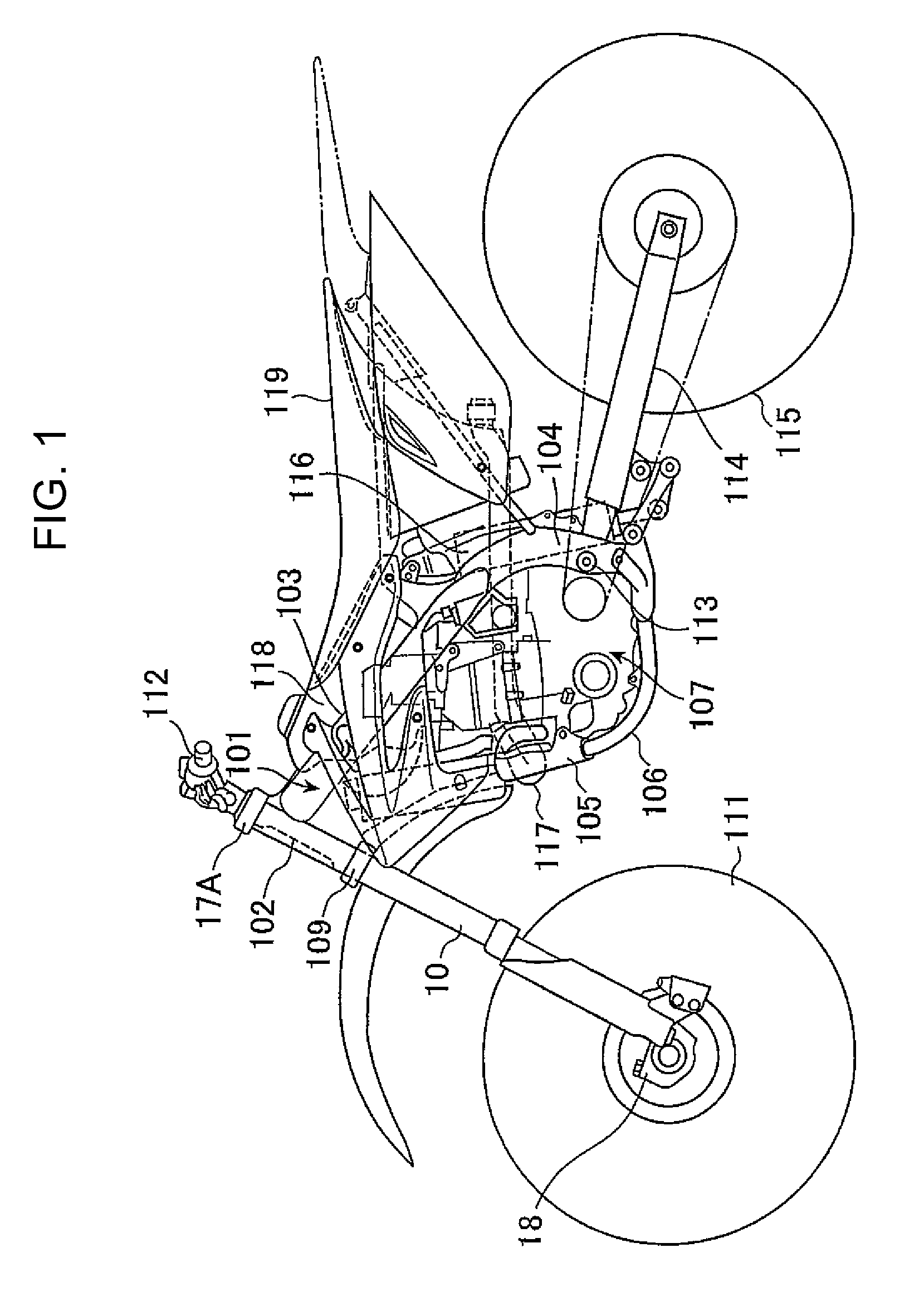
[0035]FIG. 1 shows a side view of an off-road type motorcycle to which a first illustrative embodiment of the present invention is applied. A vehicle body frame 101 of this motorcycle includes a head pipe 102, main frames 103, center frames 104, a down frame 105 and lower frames 106. These are connected in a loop form, inside of which an engine 107 is supported. The main frames 103, the center frames 104 and the lower frames 106 are provided in pairs ...


PUM


Abstract

A hydraulic shock absorber includes a damper cylinder having a hollow bore therein. A piston rod and piston separate the bore into a rod side oil chamber and a piston side oil chamber. A pressure side damping force generator is provided with a sub piston in the piston side oil chamber. A first separator is provided in a sub piston side oil chamber of the sub piston, with a communication hole that communicates between the sub piston side oil chamber and a bladder side oil chamber. A hollow bladder is mounted in the bladder side oil chamber. A blow hole is provided in the bladder side oil chamber, the blow hole being normally closed by the bladder and opening when oil enters the bladder side oil chamber such that the bladder is contracted by an oil pressure when a volume of the oil reaches a predetermined capacity.

Description

CROSS-REFERENCE TO RELATED APPLICATIONS[0001]The present invention claims priority under 35 USC §119 based on Japanese patent application No. 2009-046992 filed 27 Feb. 2009. The subject matter of this priority document is incorporated by reference herein.FIELD OF THE INVENTION[0002]The present invention relates to a hydraulic shock absorber for placement on a saddle-type vehicle in an area such as a front fork or the like, which is interposed between the vehicle body and wheel of the vehicle for absorbing a shock from a road surface.DESCRIPTION OF THE BACKGROUND ART[0003]Japanese Patent Application No. H11-280826 discloses a hydraulic shock absorber in which a vehicle body side sleeve and a wheel side tube are slidably and engagably fitted to each other, a damper cylinder is positioned to stand upright in the wheel side tube, a piston rod, which stands upright in the wheel side tube, is inserted in the damper cylinder, a rod side oil chamber and a piston side oil chamber are formed ...

Claims


Application Information

Patent Timeline
Patent Type & Authority Patents(United States)
IPC IPC(8): F16F9/50
CPCB62K25/08F16F9/088B62K2025/048
Inventor MORI, YOTARO
Owner HONDA MOTOR CO LTD
Why Eureka
Try Eureka