Heat Source Apparatus

a heat source and heat source technology, applied in the direction of burner control devices, burners, combustion regulation, etc., can solve the problems of increasing cost and damage caused by the heat of the harness, and achieve the effect of preventing the increase of cost, reducing the damage of the harness, and restrainting the temperature of the clamp

Active Publication Date: 2017-12-07
RINNAI CORP
View PDF7 Cites 7 Cited by
  • Summary
  • Abstract
  • Description
  • Claims
  • Application Information

AI Technical Summary

Benefits of technology

[0005]This invention has a problem of providing a heat source apparatus in which an increase in temperature in the clamp can be restrained by taking advantage of those water tubes for the water jacket which are disposed on the side plate of the combustion box.
[0006]In order to solve the above problem, this invention has an advantage of providing a heat source apparatus comprising: a burner; a combustion box for enclosing a combustion space for air-fuel mixture ejected from a combustion surface of the burner; a heat exchanger, disposed in the combustion box, for heating cold water; a water jacket disposed in that portion of the combustion box which lies between the burner and the heat exchanger, the water jacket being connected to the heat exchanger in order to cool the combustion box. An electrode component is mounted in that portion of a one-side side plate of the combustion box which lies between the burner and the heat exchanger, the electrode component comprising: an electrode which protrudes into the combustion box through a through-hole formed in the one-side side plate; and an insulator through which the electrode is fixedly inserted. The insulator has a flange portion which overlaps with a portion of outside surface around the through-hole in the one-side side plate and, in a state in which a packing is interposed between the flange portion and the one-side side plate, a clamp which overlaps with an outside surface of the flange portion is fastened to the one-side side plate, whereby the electrode component is mounted in position on the one-side side plate. In the above-mentioned heat source apparatus, the water tubes constituting a part of the wate

Problems solved by technology

Then, a harness including a lead wire that is connected to the electrode component may come into contact with the cla

Method used


Image

  • Heat Source Apparatus
  • Heat Source Apparatus
  • Heat Source Apparatus

Examples


Embodiment Construction

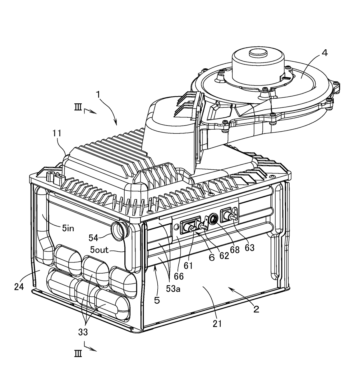
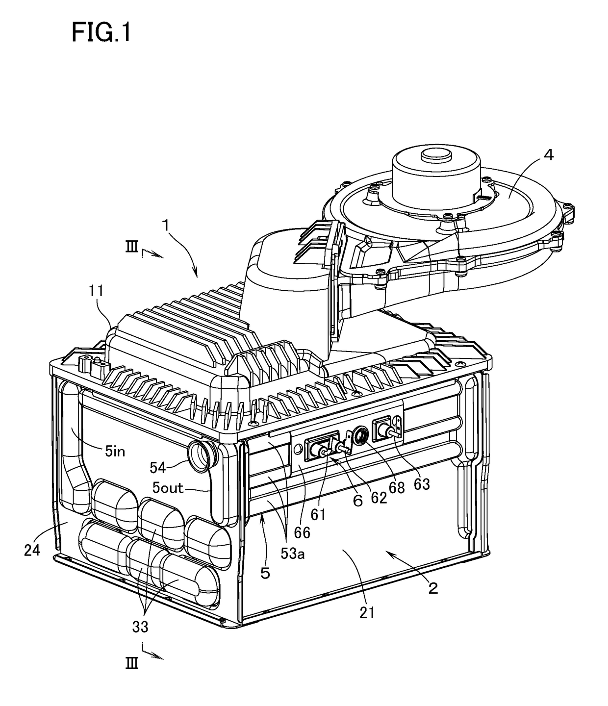
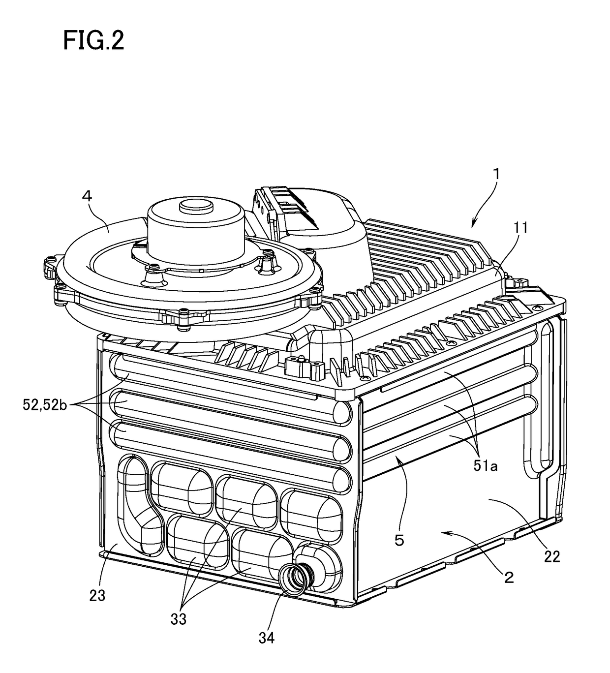
[0015]With reference to FIGS. 1 through 4, a heat source apparatus according to the first embodiment of this invention is provided with: a burner 1 of a downward posture with a combustion surface 1a facing downward; and a combustion box 2 on a lower side of the burner 1, the combustion box 2 enclosing the combustion space for the air-fuel mixture that is ejected from the combustion surface 1a. The combustion box 2 is constituted by: a side plate 21 on the front side; a side plate 22 on the rear side; a side plate 23 on laterally one side; and a side plate 24 on laterally the other (opposite) side. In the lower portion of the combustion box 2 there is housed a heat exchanger 3 which heats the cold water for supplying hot water or for heating.

[0016]The burner 1 is constituted by: a burner body 11 whose lower surface is arranged to be an open surface; and a combustion plate 12 which is mounted on the lower surface of the burner body 11 and which constitutes the combustion surface 1a. T...


PUM


Abstract

In a heat source apparatus in which an electric component having an electrode and an insulator is mounted on a side plate of a combustion box, in a state in which a packing is interposed between a flange portion of the insulator and the side plate, by fastening a clamp which overlaps with an outer surface of the flange portion, to the side plate, the temperature rise in the clamp is restrained.
Upper and lower water tubes constituting a part of a water jacket are disposed on the side plate on upper and lower sides of the position of mounting the electrode component. In case the upper and lower water tubes are disposed on an inside surface of the side plate, the upper and lower parts of the clamp are brought into contact with those disposed positions of the water tubes which are in upper and lower portions of the side plate and, in case the upper and lower water tubes are disposed on an outside of the side plate, the upper and lower parts of the clamp are brought into contact with the upper and lower water tubes.

Description

BACKGROUND OF THE INVENTION1. Technical Field[0001]The present invention relates to a heat source apparatus which is provided with: a burner; a combustion box for enclosing a combustion space for air-fuel mixture ejected from a combustion surface of the burner; and a heat exchanger, disposed in the combustion box, for heating cold water.2. Background Art[0002]As this kind of heat source apparatus, there is known one having mounted an electrode component in that portion of a side plate on one side of the combustion box which lies between the burner and the heat exchanger. The electrode component comprises: an electrode which protrudes into the combustion box through a through-hole formed in the one-side side plate; and an insulator through which the electrode is fixedly inserted (see, e.g., patent document, JP-UM-H3-30056). In this specification, the “side plate on one side” is also referred to as “one-side side plate” for brevity. In this arrangement, the insulator has a flange port...

Claims


Application Information

Patent Timeline
IPC IPC(8): F24H1/14F24H1/06F24H9/02F24H9/20
CPCF24H1/145F24H9/2035F24H9/02F24H1/06F24H1/44F24H9/1818F24H9/1836F24H2250/10F24H1/30F24H1/34F24H1/403F24H9/1809F24H9/2028F23D2208/10F23N2900/05005F23N2229/18F24H9/1832
Inventor OJIRO, TAKASHI
Owner RINNAI CORP
Why Eureka
Try Eureka