Motor control device

Active Publication Date: 2017-12-07
ROHM CO LTD
View PDF23 Cites 21 Cited by
  • Summary
  • Abstract
  • Description
  • Claims
  • Application Information

AI Technical Summary

Benefits of technology

[0008]In view of the above-mentioned problem found by the inventors of this application, it is an object of the invention

Problems solved by technology

However, this conventional example has a problem that multiple AD converters are needed.
In addition, when motor rotational speed is PWM controlled, noise or rise delay of an induced voltage (including a variation among phases) occurs at or near an on-off switch timing when a PWM on period and a PWM off period are switched.
Therefore,

Method used


Image

  • Motor control device
  • Motor control device
  • Motor control device

Examples


Embodiment Construction

[0033]

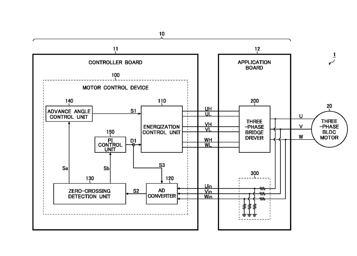
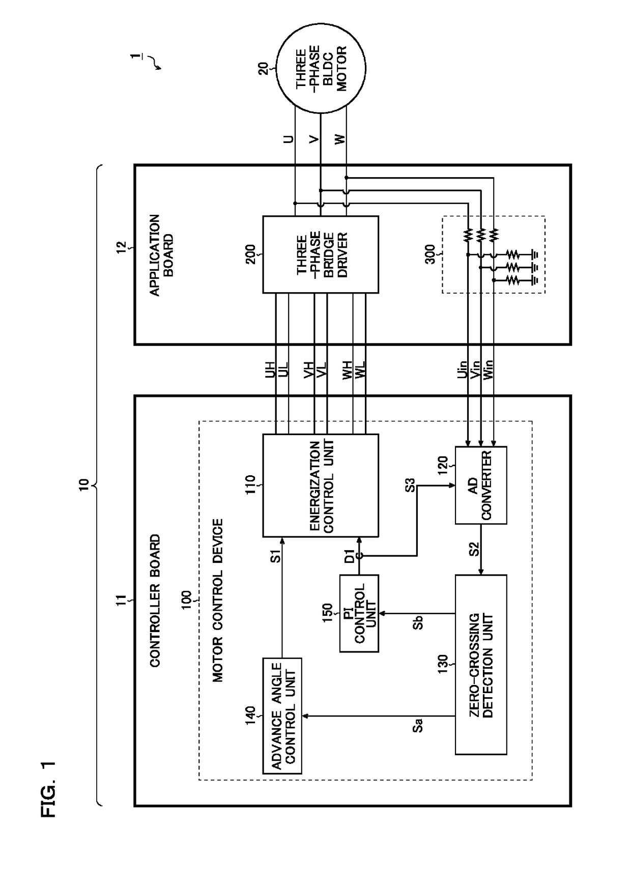
[0034]FIG. 1 is a block diagram illustrating a general structure of an electronic apparatus. An electronic apparatus 1 of this structural example includes a motor driving device 10 and a three-phase brushless DC motor 20 (hereinafter referred to simply as the motor 20).

[0035]The motor driving device 10 is a subject that drives the motor 20 without a sensor, and structural elements thereof are disposed and distributed in a controller board 11 and an application board 12. More specifically, a motor control device 100 is mounted on the controller board 11, while a three-phase bridge driver 200 (hereinafter referred to simply as the driver 200) and an adjusting unit 300 are mounted on the application board 12.

[0036]The motor control device 100 receives inputs of feedback voltages Uin, Vin, and Win from the adjusting unit 300 and generates energization control signals UH, UL, VH, VL, WH, and WL so as to output them to the driver 200.

[0037]The driver 200 receives inputs of the energ...


PUM


Abstract

A motor control device includes an energization controller that generates energization control signals of a bridge driver, an ADC that samples and converts analog feedback voltages corresponding to output voltages of the bridge driver into digital feedback signals, and a zero-crossing detector that receives the feedback signals so as to perform zero-crossing detection for determining commutation timing and PWM duty of the energization control signal. Sampling timings of the ADC are switched to one of PWM on period and PWM off period according to the PWM duty. The energization controller PWM drives lower side switches of the bridge driver, and the sampling timings of the ADC are set to the PWM off period. The ADC performs an ADC process of the feedback voltage both in the PWM on period and in the PWM off period, and the zero-crossing detector adopts one of ADC results according to the PWM duty.

Description

CROSS-REFERENCE TO RELATED APPLICATIONS[0001]This nonprovisional application claims priority under 35 U.S.C. §119(a) on Patent Application No. 2016-112650 filed in Japan on Jun. 6, 2016, the entire contents of which are hereby incorporated by reference.BACKGROUND OF THE INVENTIONField of the Invention[0002]The invention disclosed in this specification relates to a motor control device.Description of Related Art[0003]In order to drive a brushless DC motor without a sensor, it is necessary, for example, to measure counter electromotive forces of phases of the motor, to perform zero-crossing detection, and to obtain a rotational position of a rotor.[0004]Note that as an example of a conventional technique related to above description, there is JP-A-2014-87210 filed by the applicant of this application.[0005]FIG. 19 is a block diagram illustrating a conventional zero-crossing detection method (first conventional example). In the zero-crossing detection method of this diagram, each phase...

Claims


Application Information

Patent Timeline
IPC IPC(8): H02P6/182H02P27/08H02P23/00
CPCH02P6/182H02P23/0004H02P27/08H02P6/08
Inventor USAGAWA, NAOYUKINISHIYAMA, TAKAHIRO
Owner ROHM CO LTD
Why Eureka
Try Eureka