Magnetic wheel

a technology of magnetic wheels and wheels, applied in the field of magnetic wheels, can solve the problems of increasing fuel consumption, economic disadvantage, and decreasing the sailing speed of the ship

Active Publication Date: 2017-12-14
TAS GLOBAL
View PDF1 Cites 10 Cited by
  • Summary
  • Abstract
  • Description
  • Claims
  • Application Information

AI Technical Summary

Benefits of technology

[0036]According to the embodiments of the present inventions, a magnetic adsorptive force is not rapidly weakened even when the magnetic wheel is detached from a ferromagnetic floor and an effect of a magnetic field on the vicinity of the magnetic wheel can be minimized by magnetic shielding capability.

Problems solved by technology

For example, aquatic creatures adhered to the ship body may increase frictional resistance to seawater, thereby decreasing a sailing speed of the ship and increasing fuel consumption, which is at an economic disadvantage.
Since this method requires a preparation procedure to move the ship to the dock, there is a disadvantage that long cleaning time is taken and many workers are mobilized.
However, even for a diver skilled at underwater work environments, it takes a long time to clean a wide range of ship body and the level of difficulty in the cleaning work increases due to poor visibility.
However, the proposed method causes other problems of seawater pollution and detrimental effects on other marine creatures to destroy the aquatic ecosystems and is therefore forbidden by international organizations.
However, this method causes upsizing of cleaning equipment due to a propeller, which results in difficulty in efficient cleaning of the ship bottom having a large curvature, and requires many sensors used to stably move the robot along the wall of the ship body, which results in high costs.
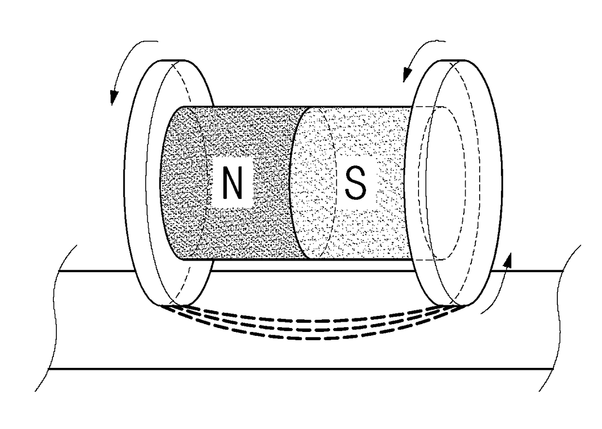
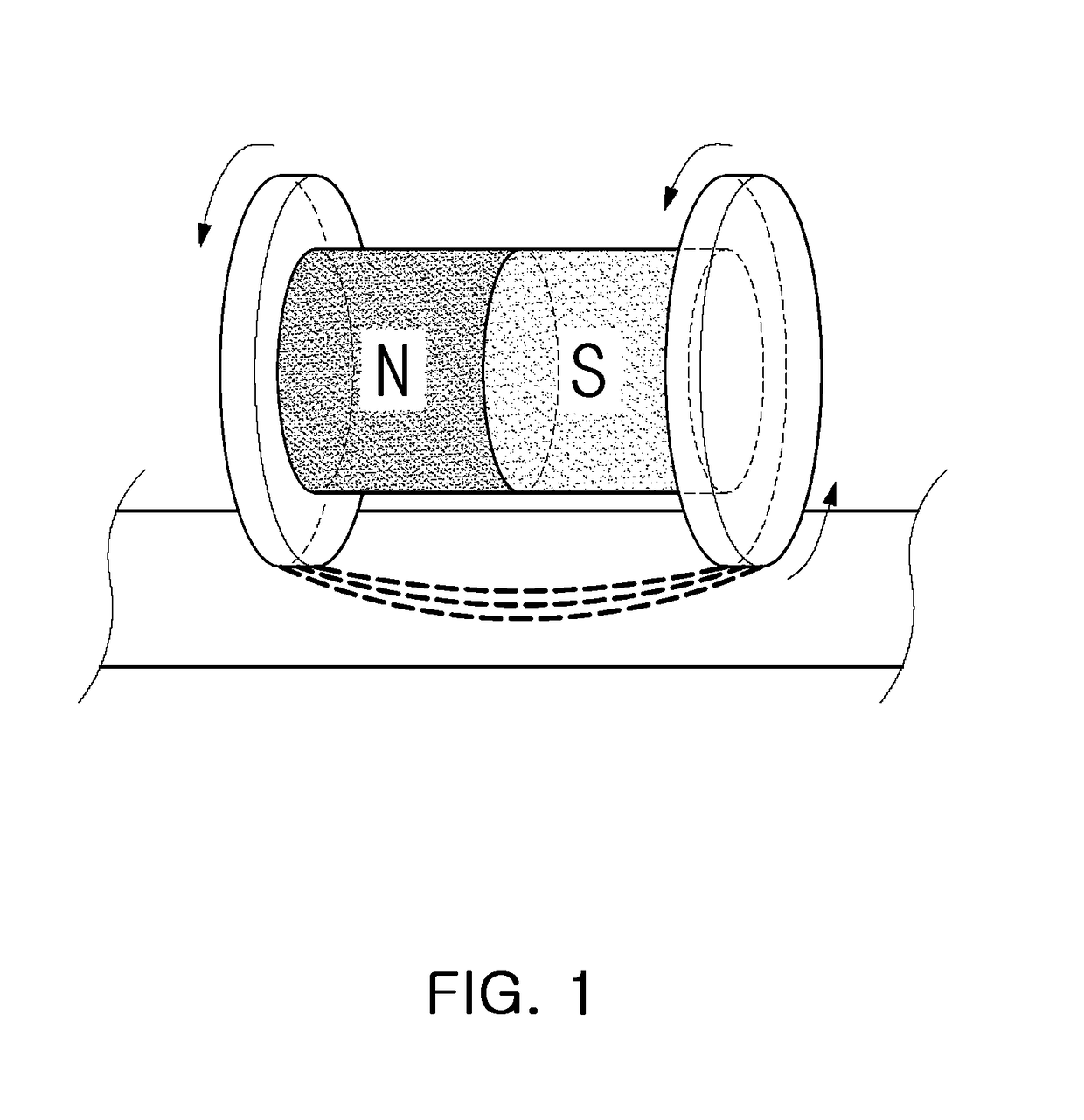
However, an adsorptive force may be rapidly weakened if there occurs an empty space between any circular plate and the floor.
However, this magnetic wheel has poor efficiency since only some of magnets used contact the floor.
If a worker is present in the vicinity of the magnetic wheel, the worker may be injured due to the magnets.
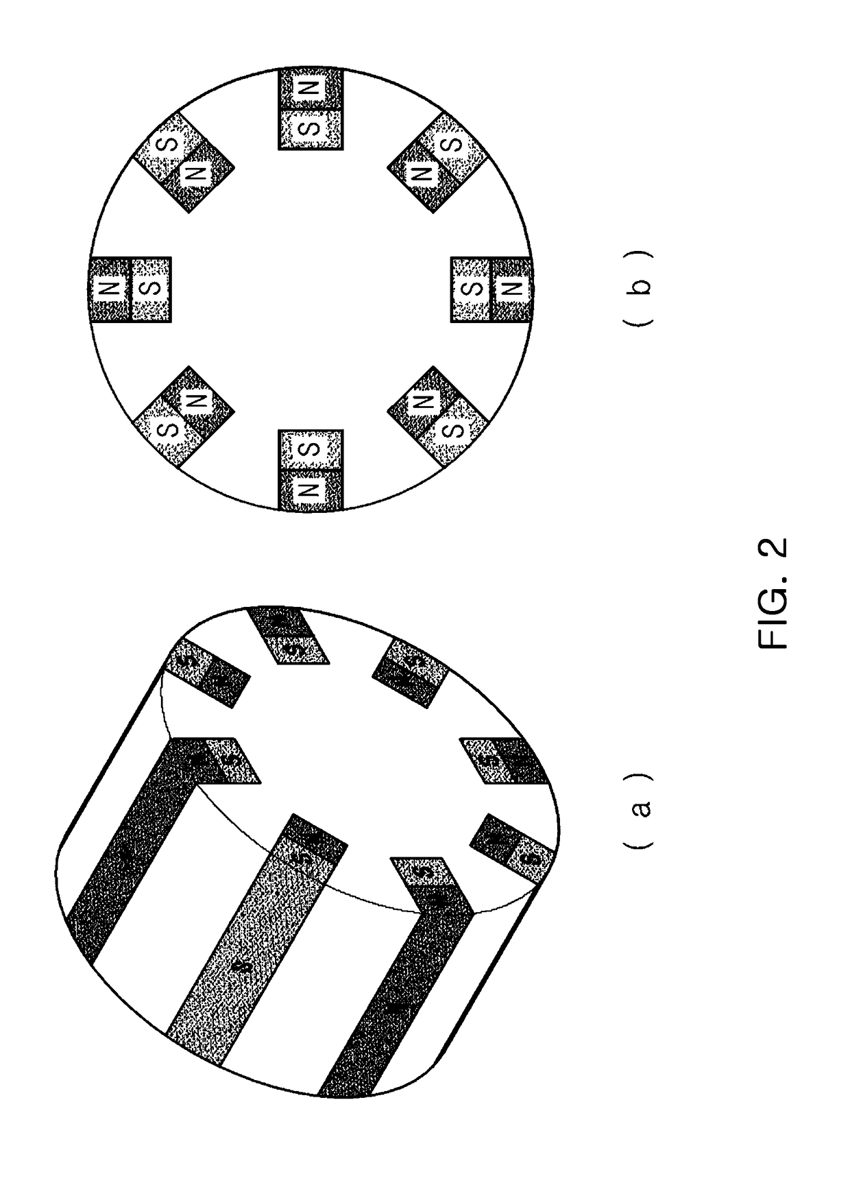
Further, when the magnetic wheel is rotated, since the magnets are arrange at constant intervals, the adsorptive force to the floor may not be uniformed.

Method used


Image

  • Magnetic wheel
  • Magnetic wheel
  • Magnetic wheel

Examples


first embodiment

[0055]FIG. 3 is a schematic perspective view a magnetic wheel according to the present invention. FIG. 4 is an exploded perspective view of FIG. 3. FIG. 5 is a side sectional view of FIG. 3. FIG. 6 is a partial exploded perspective view of FIG. 5.

[0056]As shown in these figures, a magnetic wheel 1 according to this embodiment includes a balance block 10, a magnetic body 20 which is provided in the balance block 10 and attaches the balance block 10 to an attachment object P with a magnetic force, and a magnetic shielding block 30 which is provided in the balance block 10 and guides a magnetic field generated in the magnetic body 20 toward the attachment object P.

[0057]The balance block 10 is provided in a form to be easily rotated in accordance with a weight balance of the magnetic: shielding block 30 and plays a role to maintain the bottom of the magnetic body 20 in parallel to the attachment object P (for example, the bottom of a ship) in all directions.

[0058]In this embodiment, as...

second embodiment

[0080]FIG. 9 is a schematic perspective view showing a magnetic wheel according to the present invention.

[0081]The second embodiment is different from the first embodiment in that a balance block 10a of a magnetic wheel 100 according to the second embodiment further includes a case 17 in which the block body 11 is accommodated and the frame portion 12 is removably screwed to the case 17.

[0082]As shown in FIG. 9, the case 17 may be provided in a shape corresponding to the block body and its interior may be empty to allow the block body to be accommodated therein.

[0083]In addition, a female screw thread to be screwed with a male screw thread of the frame portion may be formed in both sides of the case 17.

[0084]In addition, in the second embodiment, in order to prevent departure of the support shaft, a locking bolt may be removably joined to one or both sides of the support shaft.

third embodiment

[0085]FIG. 10 is a schematic perspective view showing a magnetic wheel according to the present invention. FIGS. 11 and 12 are state diagrams of use of the magnetic wheel shown in FIG. 10.

[0086]The third embodiment is different from the above-described embodiments in that a magnetic wheel 200 of the third embodiment includes a frame portion 12b of a balance block 10b, which is in the form of a sprocket rather than a wheel and is interlocked with chains.

[0087]In the third embodiment, as shown in FIG. 10, the frame portion 12b may be provided in the form of a sprocket and may be connected to the chains which can be rotated by the sprocket.

[0088]In addition, as shown in FIG. 12, the magnetic wheel. 200 of the third embodiment can be connected to an apparatus body for use in a ceiling and a floor as well as a wall and can be applied to a ship cleaning apparatus and a welding apparatus. This can be equally applied to following embodiments as well as the above-described embodiments.


PUM

PropertyMeasurementUnit
magnetic forceaaaaaaaaaa
magnetic fieldaaaaaaaaaa
magneticaaaaaaaaaa

Abstract

A magnetic wheel includes: a balance block; a magnetic body which is provided in the balance block and attaches the balance block to an attachment object with a magnetic force; and a magnetic shielding block which is provided in the balance block and guides a magnetic field generated in the magnetic body toward the attachment object.

Description

CROSS-REFERENCE TO RELATED APPLICATION[0001]This application claims the benefit of Korean Application No. 10-2014-0187443 filed on Dec. 23, 2014 with the Korean Intellectual Property Office, the disclosure of which is incorporated herein by reference.TECHNICAL FIELD[0002]The present invention relates to a magnetic wheel and more particularly, to a magnetic wheel rotatably attached to an attachment object including the bottom of a ship.BACKGROUND ART[0003]In general, aquatic creatures living under water, such as barnacles, sea squirts, serpula, mytilus galloprovincialis, freshwater shellfish, lagoon bugyul body, visible bluish, greener and so on, adhere to and live in a surface of the body of a ship, which does various damage to the ship.[0004]For example, aquatic creatures adhered to the ship body may increase frictional resistance to seawater, thereby decreasing a sailing speed of the ship and increasing fuel consumption, which is at an economic disadvantage.[0005]Conventionally, a...

Claims


Application Information

Patent Timeline
Patent Type & Authority Applications(United States)
IPC IPC(8): B60B19/00H01F7/02H05K9/00B08B7/00B63C5/00
CPCB60B19/006B63C5/00B08B7/00H01F7/02B60B2900/931B60B2310/302B60B2360/50B60B2380/10H05K9/0075B60B19/00B62D55/265B63B59/08B63B59/10B60B19/12B60B2310/305B60B2310/306B60B2310/311
Inventor LEE, DONG WOOK
Owner TAS GLOBAL
Why Eureka
Try Eureka