Display Device and Electronic Device

a technology of electronic devices and display devices, applied in the direction of identification means, instruments, polarising elements, etc., can solve the problems of the power consumption of display devices using batteries as power sources is required to be reduced, so as to achieve the effect of reducing the power consumption of electronic devices including display devices and reducing the power consumption of display devices

Active Publication Date: 2017-12-14
SEMICON ENERGY LAB CO LTD
View PDF0 Cites 27 Cited by
  • Summary
  • Abstract
  • Description
  • Claims
  • Application Information

AI Technical Summary

Benefits of technology

[0009]The power consumption of electronic devices including display devices is required to be reduced. In particular, the power consumption of display devices of devices using batteries as power sources is required to be reduced because the display devices consume a large amount of power.
[0011]An object of one embodiment of the present invention is to provide a display device with high visibility. Another object is to provide a display device capable of performing display by diverse methods. Another object is to provide a low-power display device. Another object is to provide a novel display device. Another object is to provide an electronic device including the display device (display panel). Another object is to provide a novel electronic device.
[0030]With one embodiment of the present invention, a display device with high visibility can be provided. Alternatively, a display device capable of performing display by diverse methods can be provided. Alternatively, a low-power display device can be provided. Alternatively, a novel display device can be provided. Alternatively, an electronic device including the display device (display panel) can be provided. Alternatively, a novel electronic device can be provided.

Problems solved by technology

In particular, the power consumption of display devices of devices using batteries as power sources is required to be reduced because the display devices consume a large amount of power.

Method used


Image

  • Display Device and Electronic Device
  • Display Device and Electronic Device
  • Display Device and Electronic Device

Examples


embodiment 1

[0072]In this embodiment, a display device and an electronic device of embodiments of the present invention will be described with reference to drawings.

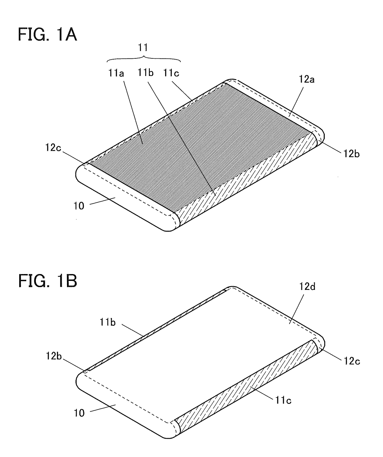
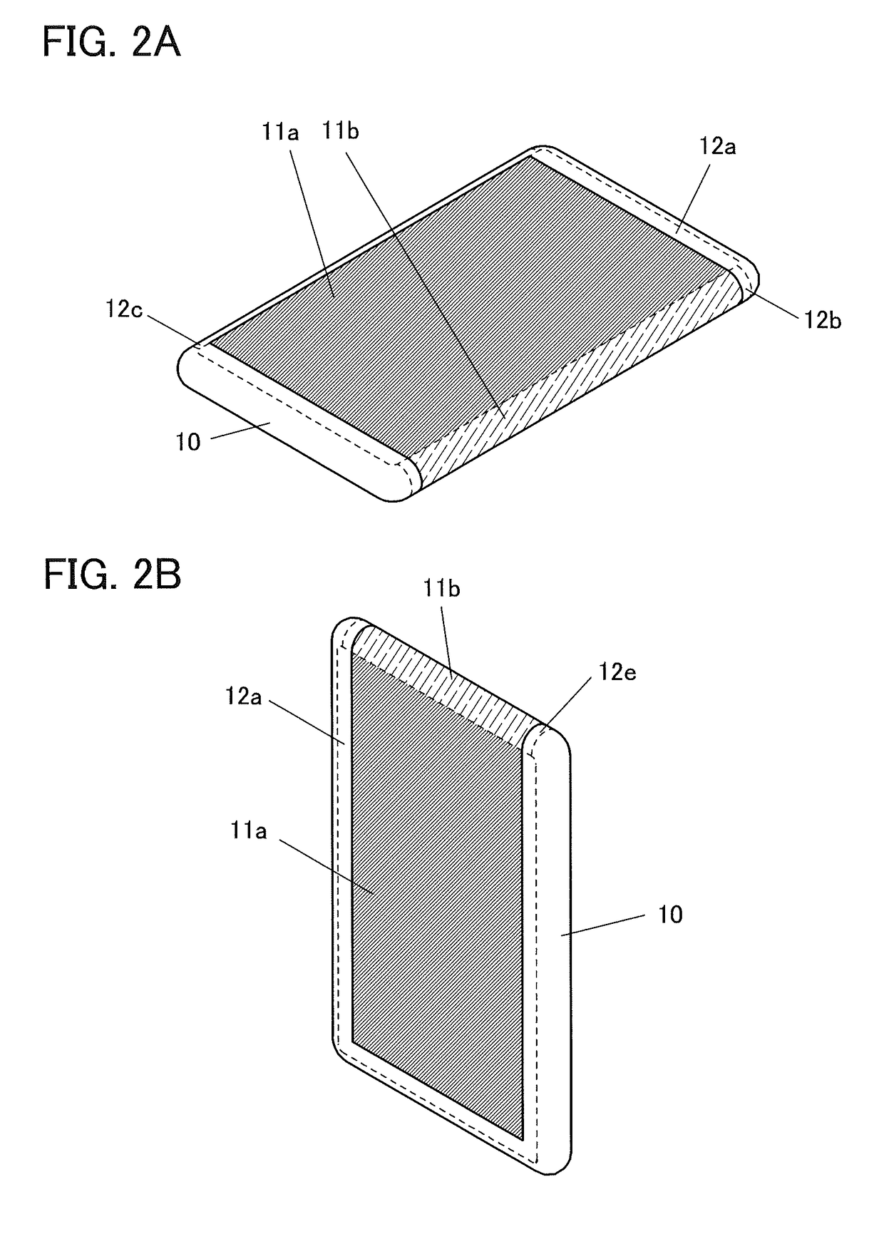
[0073]A display device of one embodiment of the present invention includes a first region and a second region adjacent to the first region. The first region is provided with a display element having a function of reflecting visible light and a display element having a function of emitting visible light. The second region is provided with a display element having a function of emitting visible light.

[0074]In an electronic device, the first region is provided for a first surface (e.g., top surface) on which a main image is displayed, and the second region is provided for a second surface (e.g., side surface) on which an auxiliary image is displayed.

[0075]In the second region, display is performed as needed and thus is not performed in normal times, which allows a reduction in power consumption. Furthermore, the structure of the displa...

embodiment 2

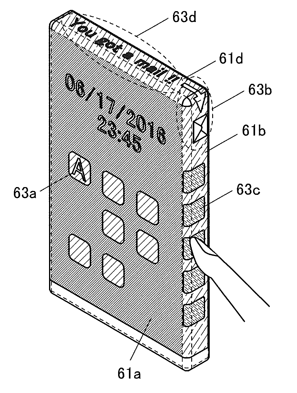
[0124]In this embodiment, a display device and an electronic device different from those in Embodiment 1 will be described with reference to drawings. Note that the detailed description of elements which are the same as those in Embodiment 1 is omitted.

[0125]A display device of one embodiment of the present invention includes a first display region, a second display region, a third display region, and a fourth display region. The first to fourth display regions are substantially quadrangular. The first display region is in contact with the second display region and the third display region. The second display region is in contact with the fourth display region. The third display region is in contact with the fourth display region.

[0126]The first to fourth display regions are each provided with a display element having a function of emitting visible light. The first display region may further be provided with a display element having a function of reflecting visible light.

[0127]In an...

embodiment 3

[0183]In this embodiment, a display device including a first display element that reflects visible light and a second display element that emits visible light will be described. The display device has a structure of either the display region 11a described in Embodiment 1 or the display region 61a described in Embodiment 2.

[0184]The display device has a function of displaying an image using one or both of first light reflected by the first display element and second light emitted by the second display element. Alternatively, the display device has a function of producing gray levels by controlling the amount of the first light reflected by the first display element and the amount of the second light emitted by the second display element.

[0185]The display device preferably includes first pixels each of which produces gray levels by controlling the amount of light reflected by the first display element and second pixels each of which produces gray levels by controlling the amount of li...


PUM

PropertyMeasurementUnit
thicknessaaaaaaaaaa
thicknessaaaaaaaaaa
wavelengthaaaaaaaaaa

Abstract

A display device includes a first region and a second region adjacent to the first region. A display element included in the first region has a function of reflecting visible light and a function of emitting visible light. A display element included in the second region has a function of emitting visible light. In an electronic device including the display device, the first region is located on a first surface (e.g., top surface) on which a main image is displayed, and the second region is located on a second surface (e.g., side surface) on which an auxiliary image is displayed.

Description

TECHNICAL FIELD[0001]The present invention relates to an object, a method, or a manufacturing method. The present invention relates to a process, a machine, manufacture, or a composition of matter. In particular, one embodiment of the present invention relates to a semiconductor device, a light-emitting device, a display device, an electronic device, a lighting device, a driving method thereof, or a manufacturing method thereof. In particular, one embodiment of the present invention relates to a display device (display panel) capable of displaying images on a curved surface. Another embodiment of the present invention relates to an electronic device, a light-emitting device, or a lighting device that includes a display device capable of displaying images on a curved surface, or a manufacturing method thereof.[0002]In this specification and the like, a semiconductor device refers to every device that can function by utilizing semiconductor characteristics. A transistor, a semiconduct...

Claims


Application Information

Patent Timeline
Patent Type & Authority Applications(United States)
IPC IPC(8): G02F1/1335G02B5/30H01L31/14G09G3/32
CPCG02F1/1335H01L31/14G09G3/32G02F1/133514G02B5/3016G02F1/133555G09G3/3233G09G3/3648G09G2300/046G09G2300/0842G02B5/30G02F1/13471G02F2201/44G02F2203/01G02F2203/02G02F2203/09G02F1/133626G02F1/13478F21S2/00G02F1/1333G09F9/00G09G3/035G09G3/20G09G2320/0686G09G2330/021
Inventor YAMAZAKI, SHUNPEIKUBOTA, DAISUKEKUSUMOTO, NAOTO
Owner SEMICON ENERGY LAB CO LTD
Why Eureka
Try Eureka