Air Flow Cooking Appliance

Active Publication Date: 2017-12-21
SEB SA
View PDF3 Cites 58 Cited by
  • Summary
  • Abstract
  • Description
  • Claims
  • Application Information

AI Technical Summary

Benefits of technology

[0025]Advantageously, the extraction window is formed by a flat screen. Such a window is simple to produce.
[0026]Advantageously, the centrifugal turbine comprises multiple paddles, and the extraction window has at least one portion arranged at a

Problems solved by technology

However, this appliance presents the particular disadvantage of having a complex internal structu

Method used


Image

  • Air Flow Cooking Appliance
  • Air Flow Cooking Appliance
  • Air Flow Cooking Appliance

Examples


Example

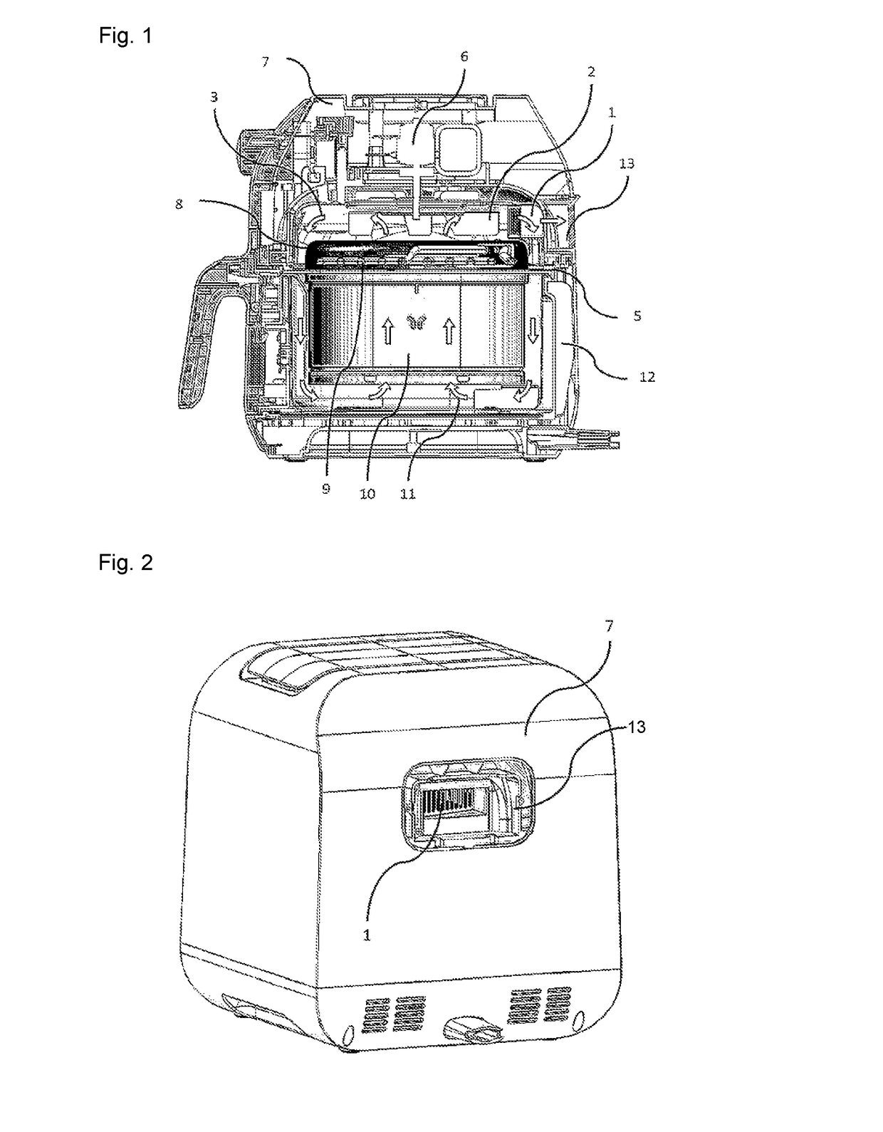
[0036]FIG. 1 depicts a cross-section view of an air flow cooking appliance, which comprises a centrifugal turbine (2), arranged in a cooking space formed by an upper cavity (3) and a reservoir (11). The reservoir (11) as well as a cooking basket (10) are removable with respect to a casing (7). These components are guided in translational movement along a guide formed by a cooking chamber (12) and a ring (5). The ensemble is removed through the front of the appliance (to the left in FIG. 1), using a gripping handle, as shown in FIG. 1.

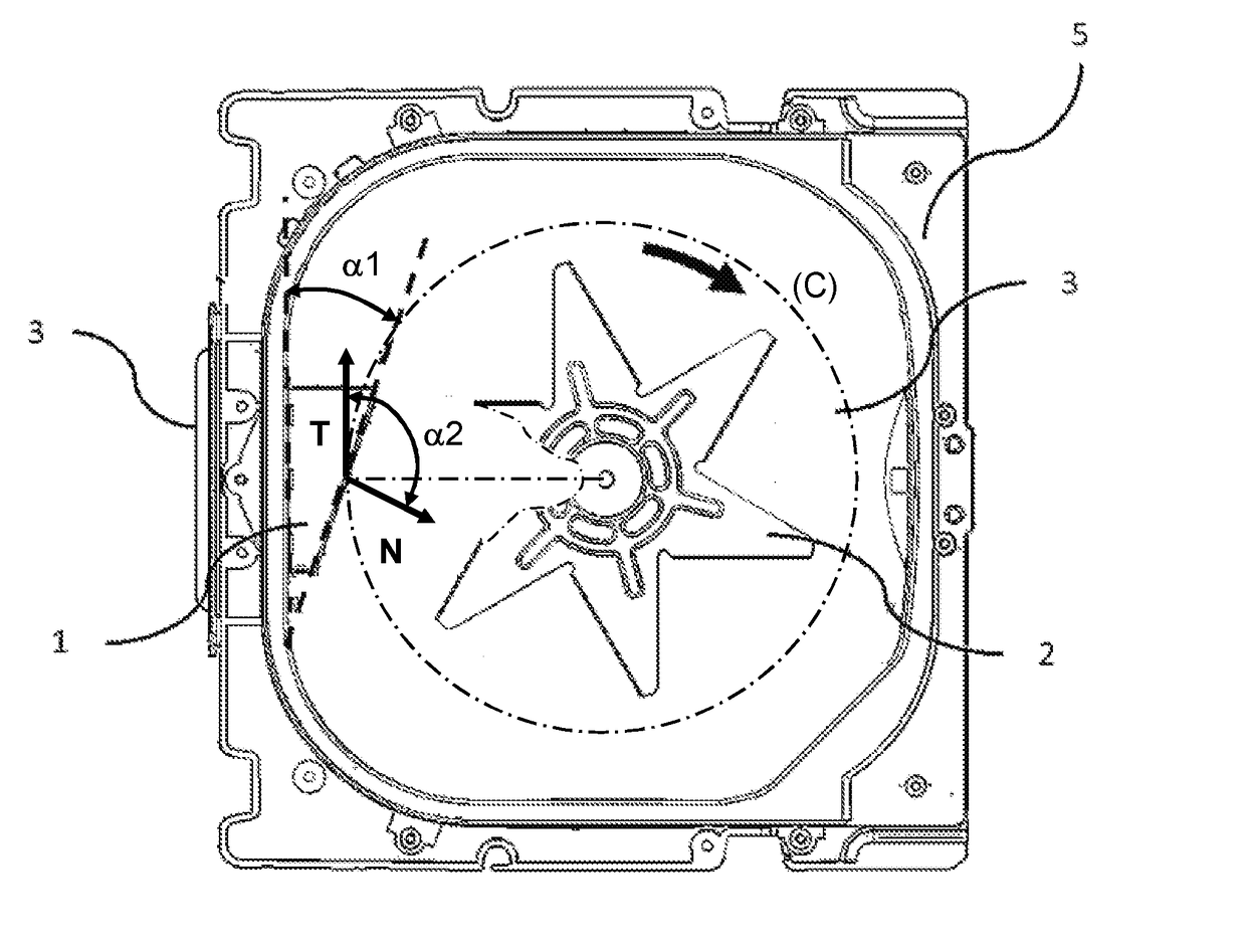
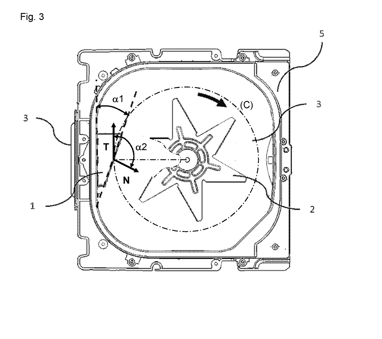
[0037]Food is cooked in the cooking basket (10). The air in the cooking space is heated by means of an element (9), and then set in motion inside this cooking space by the centrifugal turbine (2) connected to a motor (6) for this purpose. The air is drawn in by the cooking basket (10) via a deflector (8). It is heated as it passes by the element (9). The air is then propelled radially onto the walls of the upper cavity (3) by the centrifugal turbine (2)...


PUM


Abstract

Food cooking appliance comprising: a centrifugal turbine arranged to create an air flow inside a cooking space, a steam extraction window arranged so as to extract, toward the exterior of the appliance, steam present inside the cooking space, wherein the extraction window has, at every point on its passageway surface, a normal direction with at least one non-zero component along a tangential direction to a circle centered on the centrifugal turbine and passing to the center of the extraction window.

Description

CROSS-REFERENCE TO RELATED APPLICATION[0001]This application claims priority to French Patent Application No. 1655557 filed Jun. 15, 2016, the disclosure of which is hereby incorporated in its entirety by reference.FIELD OF THE INVENTION[0002]This invention pertains generally to a household cooking appliance, and in particular to a portable or transportable air flow cooking appliance.DESCRIPTION OF RELATED ART[0003]In the prior art, there exist convection or air flow cooking appliances, such as the one described in patent document WO 2012032449 A1. However, this appliance presents the particular disadvantage of having a complex internal structure, yet without being able to effectively release steam generated while the food is being cooked.[0004]One objective of this invention is to remedy the disadvantages of the prior art mentioned above, and in particular, firstly, to propose an air flow cooking appliance with a simple internal structure that can effectively release steam present ...

Claims


Application Information

Patent Timeline
IPC IPC(8): A47J37/06F24C15/32
CPCA47J37/0641A47J37/06F24C15/322A47J37/0664F24C15/325
Inventor MUHR, NICOLASQUINARD, JEREMY
Owner SEB SA
Why Eureka
Try Eureka