Torque transmission device, more particularly for a motor vehicle

Inactive Publication Date: 2017-12-21
VALEO EMBRAYAGES SAS
View PDF3 Cites 7 Cited by
  • Summary
  • Abstract
  • Description
  • Claims
  • Application Information

AI Technical Summary

Benefits of technology

[0016]The invention more particularly aims at providing a si

Problems solved by technology

The break of slope between the first and second portions of the curve may generate vibrations and a significant hysteresis upon operation of the torque converter which might aff

Method used


Image

  • Torque transmission device, more particularly for a motor vehicle
  • Torque transmission device, more particularly for a motor vehicle
  • Torque transmission device, more particularly for a motor vehicle

Examples


Embodiment Construction

)

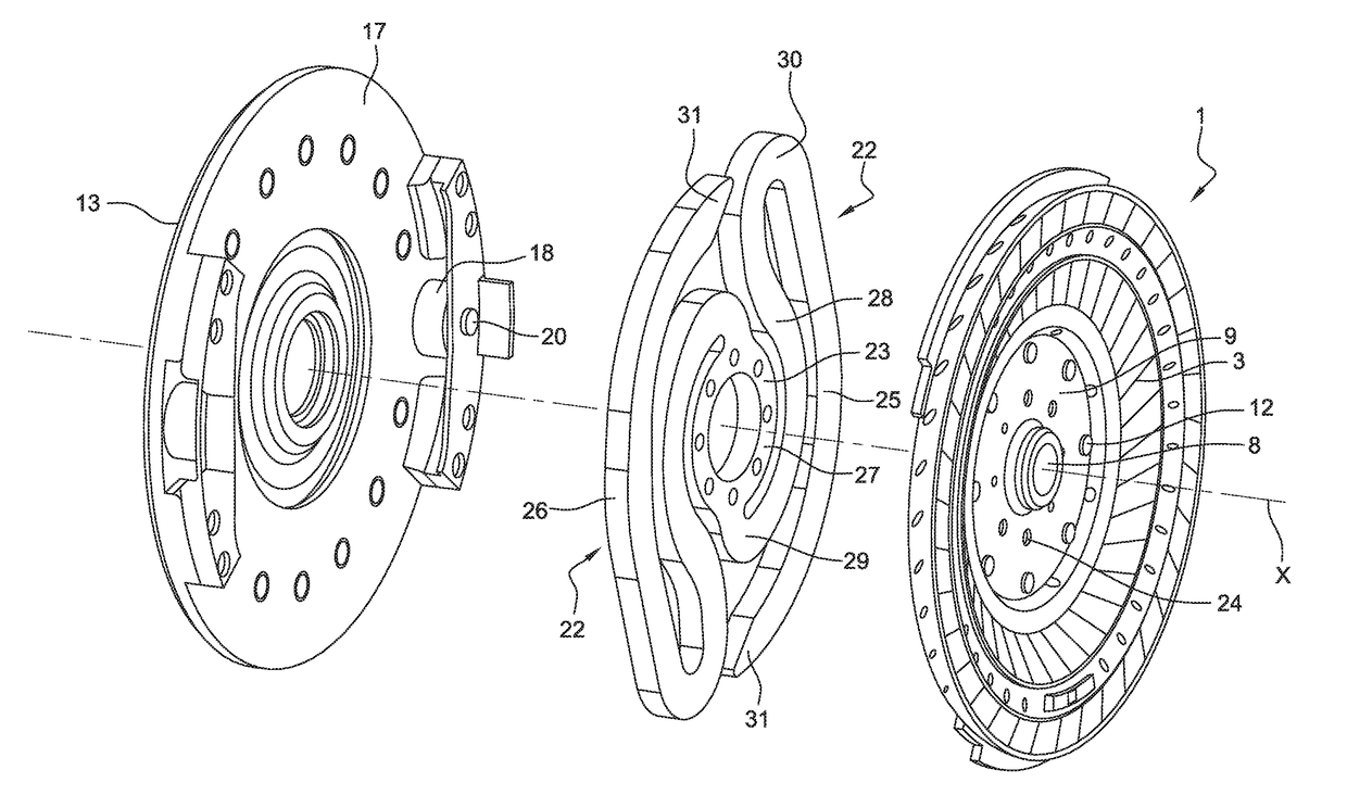
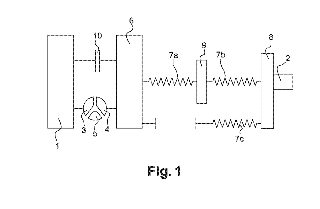
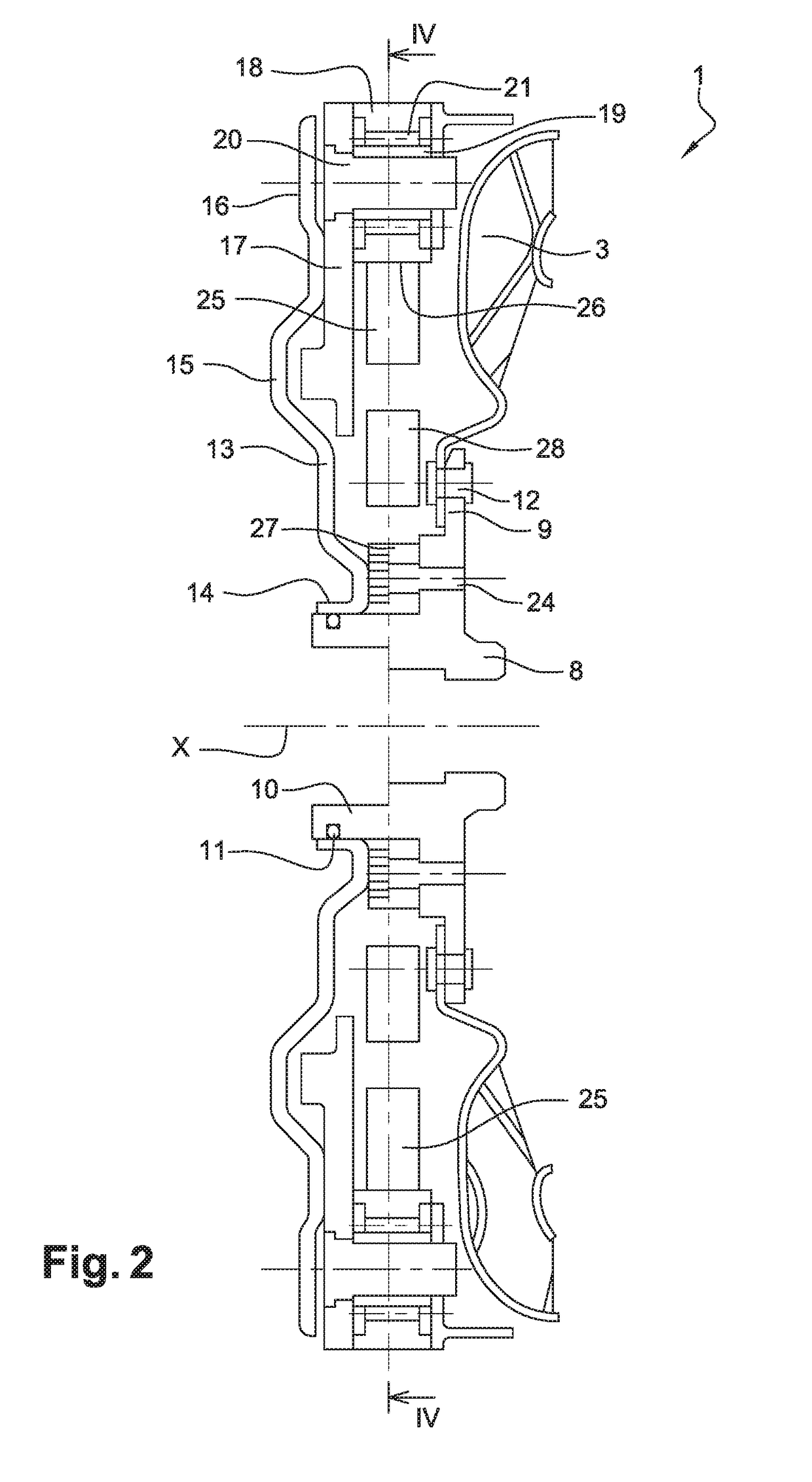
[0056]FIGS. 2 to 6 illustrate a hydrokinetic torque coupling device for a motor vehicle, according to one embodiment of the invention. The hydrokinetic torque coupling device is more particularly a hydrodynamic torque converter. Such device makes it possible to transmit a torque from the output shaft of an internal combustion engine in a motor vehicle, such as for instance a crankshaft 1, to a transmission input shaft 2. The axis of the torque converter bears reference X.

[0057]In the following, the words “axial”, “radial” and “circumferential” are defined relative to the X axis.

[0058]The torque converter conventionally comprises an impeller bladed wheel 3, able to hydrokinetically drive a turbine bladed wheel 4 through a reactor 5.

[0059]The impeller wheel 3 is attached to a cover (not shown) which defines an internal volume accommodating the impeller wheel 3, the turbine wheel 4 and the reactor 5. Said cover comprises attaching means making it possible to rotationally couple said c...


PUM


Abstract

The invention relates to a torque transmission device, more particularly for a motor vehicle, comprising a torque input element (15, 17) and a torque output element (8) able to pivot about an axis (X) with respect to one another, at least one elastic leaf (22), rotationally coupled to the torque output element (8) or to the torque input element (15, 17) respectively, the elastic leaf (22) being able to be elastically and radially held to rest on a supporting member (18) carried by the torque input element (15, 17) or the torque output element (8) respectively, the elastic leaf (22) being able to bend upon rotation of the torque input element (15, 17) with respect to the torque input element (8).

Description

FIELD OF THE INVENTION[0001]The present invention relates to a torque transmitting device and a hydrokinetic torque coupling device for a motor vehicle, such as a torque converter, for instance.BACKGROUND OF THE INVENTION[0002]A known hydrodynamic torque converter is schematically and partially illustrated in FIG. 1 and makes it possible to transmit a torque from the output shaft of an internal combustion engine in a motor vehicle, such as for instance a crankshaft 1, to a transmission input shaft 2.[0003]The torque converter conventionally comprises an impeller wheel 3, able to hydrokinetically drive a turbine wheel 4 through a reactor 5.[0004]The impeller wheel 3 is coupled to the crankshaft 1 and the turbine wheel 4 is coupled to guiding washers 6.[0005]A first group of elastic members 7a, 7b of the compression spring type is mounted between the guiding washers 6 and a central hub 8 is coupled to the transmission input shaft 2. The elastic members 7a, 7b of the first group are ar...

Claims


Application Information

Patent Timeline
IPC IPC(8): F16H45/02F16D25/06F16F15/121
CPCF16H45/02F16H2045/0221F16D25/06F16F15/1215F16F15/1213F16F2230/0064F16H2045/0205F16H2045/0278F16F15/1333F16F15/1336
Inventor DURHAM, PATRICK
Owner VALEO EMBRAYAGES SAS
Why Eureka
Try Eureka