Detection And Elimination Of Stress Singularity

a technology of stress singularity and elimination, which is applied in the field of detection and elimination of stress singularity, can solve the problems of stress singularity, a common difficulty in such convergence practice, and the increase of numerical errors with smaller mesh elements, so as to eliminate stress singularity, eliminate stress singularity, and rapid change of stress gradient

Active Publication Date: 2017-12-21
DASSAULT SYST SOLIDWORKS CORP
View PDF1 Cites 3 Cited by
  • Summary
  • Abstract
  • Description
  • Claims
  • Application Information

AI Technical Summary

Benefits of technology

[0009]Other embodiments include a computer-aided design (CAD) system having a processor operatively coupled to a data storage system and a data storage memory operatively coupled to the processor. In such embodiments, the data storage system stores a three-dimensional model, and the data storage memory comprises instructions to configure the processor to detect a potential area of high stress in which an element having a high stress value in the potential area has surrounding elements with a rapid change of stress value, refine a finite element mesh of the 3D CAD model in at least the potential area of high stress, and determine that after the refining step the high stress value does not converge. Instructions also configure the processor to alert a user that the potential area of high stress is an area having one or more elements of stress singularity, suggest to the user how to eliminate the stress singularity, and enable the user to modify the design of the 3D CAD model to eliminate the stress singularity.
[0011]To detect the potential area of high stress, aspects of the invention narrow an analysis of finite elements to those finite elements having higher strain values than other ones of the finite elements and / or analyze a local area of a part in the 3D CAD model. Other aspects of the invention include analyzing the 3D model to locate geometry forming sharp angles, visually indicating the area of stress singularity, and suggesting to the user removing sharp angled geometry, creating a new geometric entity, and changing a load to eliminate stress singularity. Suggesting to the user may take the form of one or both of a tool tip and a table. Moreover, an embodiment of the invention may integrate a finite element analysis process and a computer-aided design system, and automatically change the underlying 3D CAD model upon the user choosing a suggestion of how to eliminate the stress singularity.

Problems solved by technology

Stress singularity, however, is a common difficulty in such convergence practice.
Stress singularity occurs when numerical errors increase with smaller mesh elements.

Method used


Image

  • Detection And Elimination Of Stress Singularity
  • Detection And Elimination Of Stress Singularity
  • Detection And Elimination Of Stress Singularity

Examples


Embodiment Construction

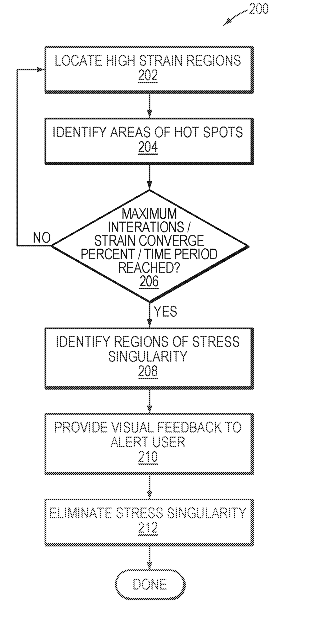
[0025]The present invention automatically detects and identifies stress singularity and other common finite element analysis (FEA) difficulties, such as material, mesh, and stress concentration. After detecting one or more areas where stress is locally high, the present invention suggests and automatically adjusts a 3D model and simulation setup to eliminate stress singularity. Moreover, the inventive concepts described herein provide a self-learning process to extend a user's knowledge and experiences.

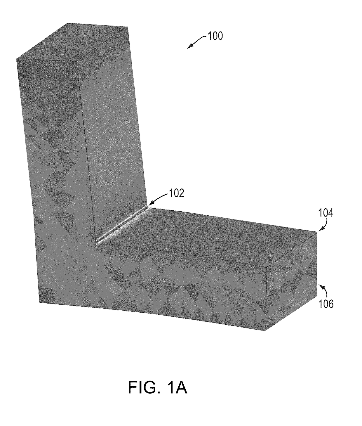
[0026]Referring now to FIGS. 1a, 1b, and 1c, certain causes of stress singularity are illustrated, by way of non-limiting example. FIG. 1a shows a 3D model 100 having a sharp corner 102 that causes stress singularity, which is indicated by the yellow and red coloring of the sharp corner 102. Areas of non-sharp corners and edges (e.g., non-sharp corner 104 and non-sharp edge 106) are indicated in a green or blue.

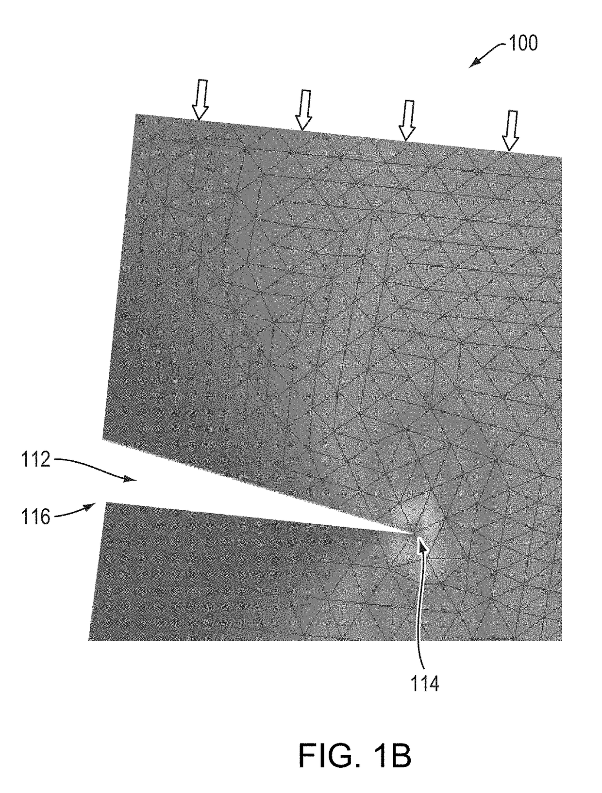
[0027]In FIG. 1b, a 3D model 110 contains a sharp cut 112. The sharp cut 1...


PUM


Abstract

A computer-implemented method and system automatically detects stress singularity in a three-dimensional (3D) computer-aided design (CAD) model. A potential area of high stress is detected. A finite element mesh of the 3D CAD model is refined, at least in the potential area of high stress, after which, whether the high stress value converges is determined. A user is alerted that the potential area of high stress is an area having one or more elements of stress singularity. Suggestions are made regarding how to eliminate the stress singularity and the user is enabled to modify the design of the 3D CAD model to eliminate the stress singularity.

Description

RELATED APPLICATION(S)[0001]This application claims the benefit of U.S. Provisional Application No. 62 / 351,751, filed on Jun. 17, 2016. The entire teachings of the above application(s) are incorporated herein by reference.BACKGROUND OF THE INVENTION[0002]Computer-aided design (CAD) software allows a user to construct and manipulate complex three-dimensional (3D) models. A number of different modeling techniques can be used to create a 3D model. One such technique is a solid modeling technique, which provides for topological 3D models where the topological entities have corresponding supporting geometrical entities.[0003]A design engineer designs physical and aesthetic aspects of 3D models, and is skilled in 3D modeling techniques. The design engineer creates parts and may assemble the parts into a subassembly or an assembly. A subassembly may also consist of other subassemblies. An assembly is designed using parts and subassemblies. Parts and subassemblies are hereinafter collective...

Claims


Application Information

Patent Timeline
Patent Type & Authority Applications(United States)
IPC IPC(8): G06F17/50
CPCG06F17/50G06F30/00G06F30/23
Inventor HUANG, LI-LINGNIMMAGADDA, PRASADCHIRLA, SUBBI REDDYDATTI, NANDISH
Owner DASSAULT SYST SOLIDWORKS CORP
Why Eureka
Try Eureka