Power supply device and vehicle provided with same

Active Publication Date: 2017-12-21
SANYO ELECTRIC CO LTD
View PDF5 Cites 5 Cited by
  • Summary
  • Abstract
  • Description
  • Claims
  • Application Information

AI Technical Summary

Benefits of technology

[0006]The present invention addresses these disadvantages of the conventional power supply devices. One of the obj

Problems solved by technology

When a metal frame or a metal case component is used, however, the weight is heavy, and a disadvantage is caused in terms of fuel consumption and travelling performance.
Furthermore, a metal case cannot take a comp

Method used


Image

  • Power supply device and vehicle provided with same
  • Power supply device and vehicle provided with same
  • Power supply device and vehicle provided with same

Examples


Example

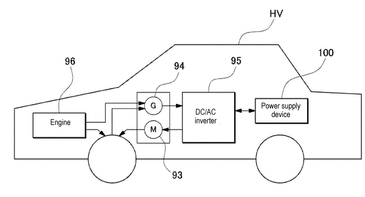
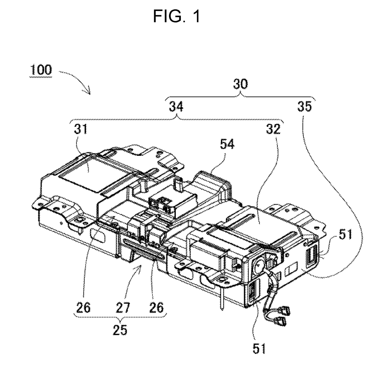
[0038]FIG. 1 to FIG. 9 show power supply device 100 in accordance with a first exemplary embodiment of the present invention. Power supply device 100 shown in these drawings shows an example of an on-vehicle power supply device. Specifically, power supply device 100 is mounted mainly in an electric vehicle such as a hybrid car or an electric car, and is used as a power source that supplies power to a travel motor of the vehicle and makes the vehicle travel. The power supply device of the present invention can be also used for an electric vehicle other than the hybrid car and electric car, and can be also used for an application requiring a high power, other than the electric vehicle.

(Power Supply Device 100)

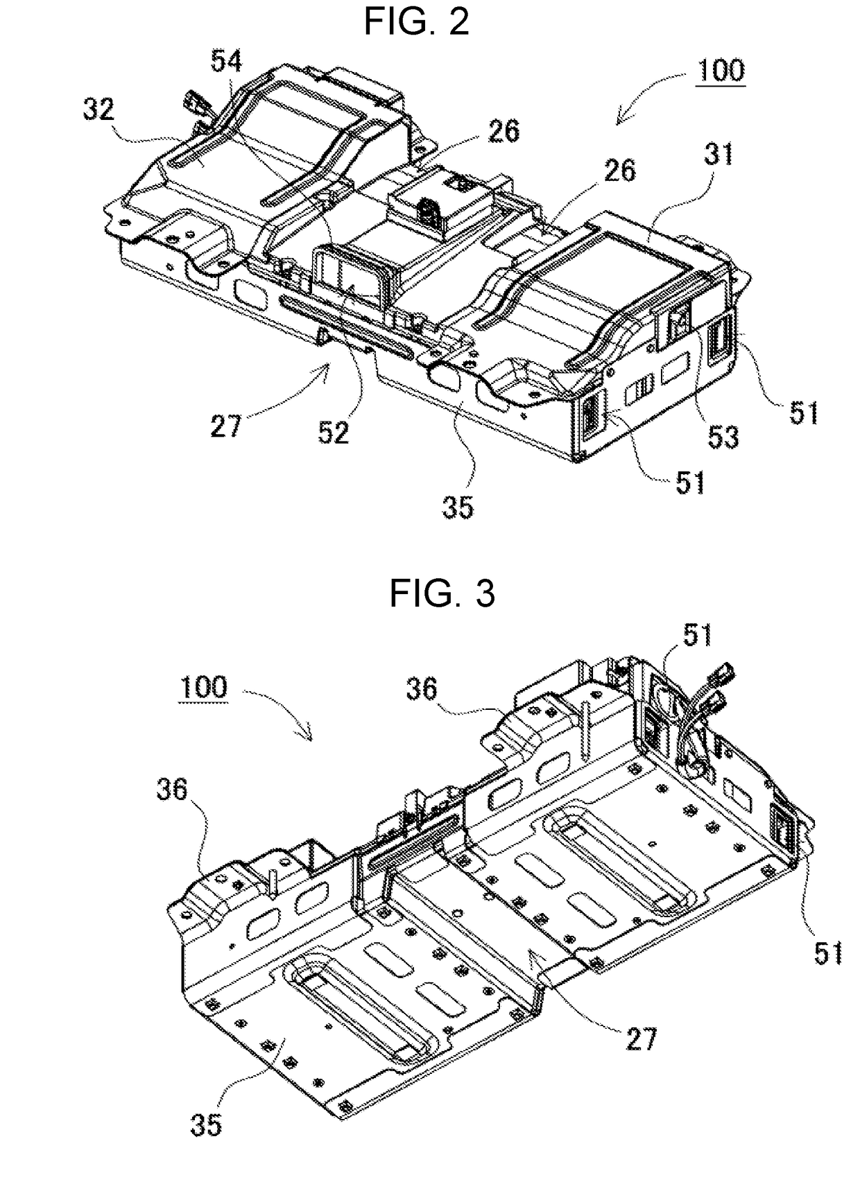
[0039]As shown in FIG. 1 to FIG. 6, the appearance of power supply device 100 has a substantially box shape extended in one direction. As shown in the exploded perspective view of FIG. 6, power supply device 100 is configured so that the upside and downside of resin-made battery ...


PUM


Abstract

In order to provide a power supply device having a high rigidity and a light weight, power supply device includes: one or more cell stacked bodies each formed by stacking secondary battery cells; a circuit board including a control circuit electrically connected to the cell stacked bodies; resin-made battery case for storing the cell stacked bodies and circuit board; metal-made lower frame for covering the bottom surface of battery case; and metal-made upper frame for covering the upper surface of battery case. Battery case has a waterproof structure. Battery case is grasped by connecting upper frame to lower frame.

Description

TECHNICAL FIELD[0001]The present invention relates to a power supply device and a vehicle equipped with the power supply device, for example relates to a power supply device of a motor that is mounted in an electric vehicle such as a hybrid car, an electric car, or an electric motorcycle, and makes the vehicle travel.BACKGROUND ART[0002]A power supply device formed by interconnecting a plurality of secondary battery cells in series or in parallel is used for a vehicle. Such a power supply device mainly employs a structure where a module such as secondary battery cells and a high-voltage component such as a circuit board are stored and fixed in a metal frame or a metal case. Especially, a power supply device for vehicles requires strength enough to withstand a vibration or impact while holding the module and high-voltage component as heavy objects. In a situation requiring such a high rigidity, the frame or case is typically made of a metal member.[0003]When a metal frame or a metal ...

Claims


Application Information

Patent Timeline
IPC IPC(8): H01M10/6563H01M10/42H01M10/625H01M10/613H01M10/647H01M10/6557H01M2/10B60L50/64
CPCH01M10/6563H01M2/10H01M10/613H01M2220/20H01M10/647H01M10/6557H01M10/4257H01M10/625H01M10/425H01M10/667B60L50/64Y02T10/70Y02E60/10H01M50/24H01M50/204H01M50/249H01M50/296H01M50/224H01M50/284H01M50/262H01M50/276H01M50/227
Inventor OKADA, WATARUUETA, YOSHIAKISUGAWARA, SHUICHISHIOTSU, YOSHIHIRO
Owner SANYO ELECTRIC CO LTD
Why Eureka
Try Eureka