This helps you quickly interpret patents by identifying the three key elements:
Problems solved by technology
Method used
Benefits of technology
Benefits of technology
The patent text describes a repeater that can efficiently transfer frames that are simultaneously received from multiple ports. This means that the same address frames, which are frames with the same address, can be transmitted efficiently. This helps to ensure that all frames are able to be quickly and easily processed by the repeater.
Problems solved by technology
Further if such a restriction arises, each of the same address frames simultaneously received from two or more ports, i.e., the frames simultaneously transmitted from many nodes to the same address cannot be efficiently transmitted to the node of the destination address.
Method used
Image
Click on the blue label to locate the original text in one second.
Reading with bidirectional positioning of images and text.
Examples
first embodiment
1. First Embodiment
[0019][1-1. Configuration]
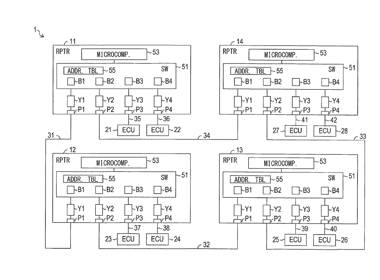
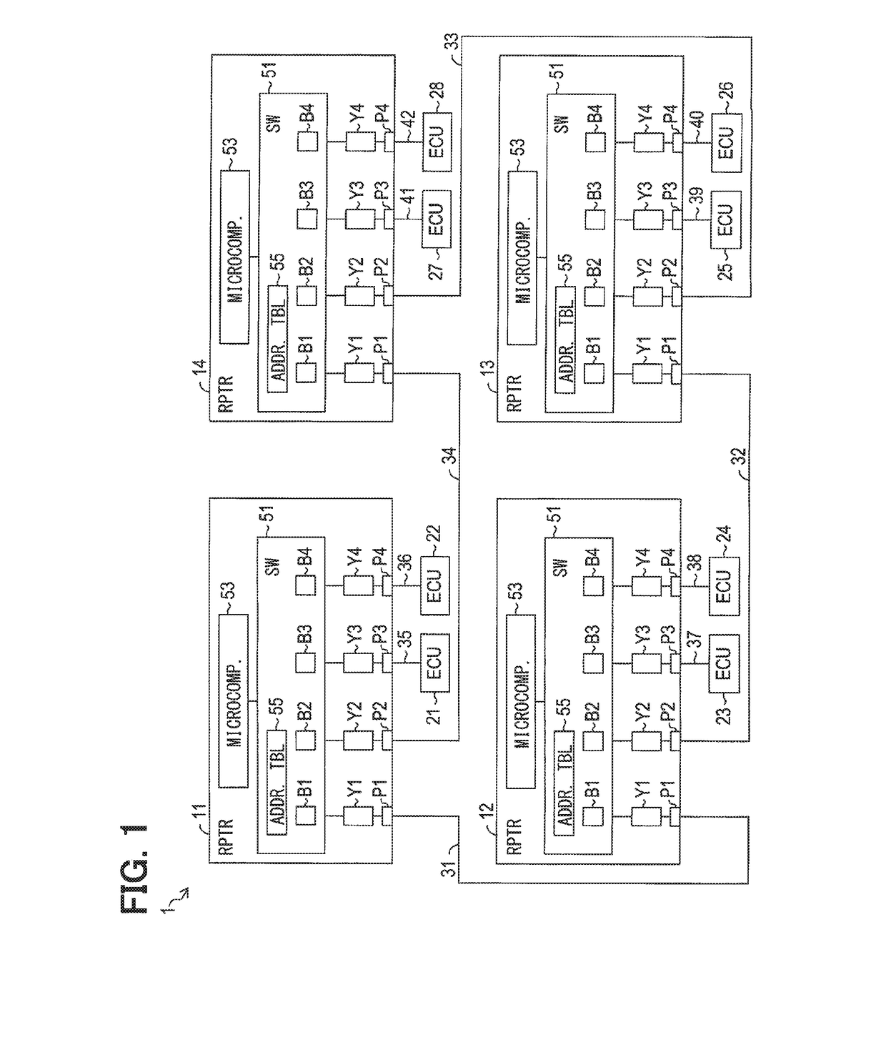
[0020]A communication network 1 of the first embodiment shown in FIG. 1 is the Ethernet network disposed in, for example, a vehicle, e.g., a passenger vehicle, and serves as a communications system in the vehicle.
[0021]As shown in FIG. 1, the communication network 1 is provided with repeaters 11-14, Electronic Control Units (ECUs) 21-28 respectively serving as a communication node, and communication lines 31-42.
[0022]The repeaters 11-14 are provided with a function to serve as an Ethernet switch to relay communications between the ECUs 21-28.
[0023]Further, the repeaters 11-14 are provided with a plurality of ports for transmitting and receiving frames. The repeaters 11-14 are provided with four ports P1-P4 in the example of the present embodiment. The repeaters 11-14 are provided with a switch part 51, respectively. The switch part 51 performs a relay process for relaying the communications according to the Ethernet standard.
[0024]The rep...
second embodiment
2. Second Embodiment
[0113][2-1. Difference of the Second Embodiment from the First Embodiment]
[0114]The configuration of the second embodiment is basically the same as that of the first embodiment, with a difference discussed below.
[0115]The same numerals are used for the same components / configurations as the first embodiment, thereby not repeating the same descriptions.
[0116][2-1-1. Configuration]
[0117]A communication network 60 of the second embodiment shown in FIG. 4 is provided with repeaters 61-68 and ECUs 71-76. The ECUs 71-75 are connected to the repeater 61. The ECU 76, which may be a destination address of the frame from the ECUs 71-75, is connected to the repeater 63. Further, at a position between the repeater 61 and the ECU 76, there are three communication paths, i.e., the first to third communication paths R1-R3.
[0118]The number of the repeaters, the ECUs, and the communication paths described above is an example.
[0119]The first communication path R1 is a path of “repe...
PUM
Abstract
A repeater for transferring same-destination frames that are addressed to a destination Electronic Control Unit (ECU) efficiently by receiving the frames from respectively different ports, includes: four ports; and a switcher, wherein the first and second ports respectively originating a communication path to an individual ECU, and the third and fourth ports respectively connected to an individual ECU that is different from the one connected the first and second ports, and when the same-destination frames are received by the third and fourth ports of the repeater at the same time, the switcher distributes the same-destination frames among the first and second ports to be transferred via two, i.e., different, communication paths toward one, i.e., same, destination ECU.
Description
CROSS REFERENCE TO RELATED APPLICATION[0001]The present application is based on and claims the benefit of priority of Japanese Patent Application No. 2016-118914, filed on Jun. 15, 2016, the disclosure of which is incorporated herein by reference.TECHNICAL FIELD[0002]The present disclosure generally relates to a repeater for organizing a communication network.BACKGROUND INFORMATION[0003]For example, in a patent document, Japanese Patent Laid-Open No. 2010-509825 (patent document 1), an idea of frame transfer between the nodes via a shortest path in an Ethernet network is disclosed (Ethernet: registered trademark). The shortest path is a shortest communication path in which the number of repeaters through which the frames pass to reach a destination node (i.e., a relay number, or “HOPS”) takes the minimum value.[0004]In the repeater that adopts the idea of the patent document 1, when frames with the same address are received simultaneously from two or more ports, each of the received...
Claims
Application Information
Patent Timeline
Application Date:The date an application was filed.
Publication Date:The date a patent or application was officially published.
First Publication Date:The earliest publication date of a patent with the same application number.
Issue Date:Publication date of the patent grant document.
PCT Entry Date:The Entry date of PCT National Phase.
Estimated Expiry Date:The statutory expiry date of a patent right according to the Patent Law, and it is the longest term of protection that the patent right can achieve without the termination of the patent right due to other reasons(Term extension factor has been taken into account ).
Invalid Date:Actual expiry date is based on effective date or publication date of legal transaction data of invalid patent.

