Deposition apparatus for organic el and evaporating apparatus

Inactive Publication Date: 2010-01-07
TOKYO ELECTRON LTD
View PDF6 Cites 1 Cited by
  • Summary
  • Abstract
  • Description
  • Claims
  • Application Information

AI Technical Summary

Benefits of technology

[0016]In accordance with the present disclosure, the heat of the heater can be transferred to the film forming material efficiently, and a vaporization rate of

Problems solved by technology

However, since a heater for heating vapor of a film forming material in an evaporating head is also placed in a depressurized space, heat of the heater may not be sufficiently transferred to the film forming material due to a heat insulation by

Method used


Image

  • Deposition apparatus for organic el and evaporating apparatus
  • Deposition apparatus for organic el and evaporating apparatus
  • Deposition apparatus for organic el and evaporating apparatus

Examples


Example

EXPERIMENTAL EXAMPLE 1

[0061]As illustrated in FIG. 11, a mica heater having a size of 45 mm×211.5 mm was accommodated in a housing having a size of 68 mm×260 mm. Then, measured were temperatures of points A-1, A-2 and A-3 at a surface A which is a surface to be heated (a surface of a path of vapor) and a temperature of a point H-1 which is a central point of the heater itself and a temperature of a point B-1 at a rear surface (surface B) of an end portion of the heater. The heater was a mica heater, and a thickness of the heater was 1.5 mm. A thickness of a heater receiving member was 1.6 mm having a clearance of 0.1 mm with respect to the thickness of the heater.

[0062]As for an installation method of the heater in accordance with an example of the present disclosure as illustrated in FIG. 12A, a rear surface of a heater 100 was firmly pressed toward a surface (surface A) to be heated by a disk spring 110 via a pressing plate 111 interposed therebetween. The experiment was conducted...


PUM

PropertyMeasurementUnit
Temperatureaaaaaaaaaa

Abstract

Provided is a deposition apparatus for organic EL capable of allowing vapor of a film forming material to be vapor deposited on a target object to be uniformly heated. A deposition apparatus, which performs a film forming process by vapor depositing a film forming material on a target object in a depressurized processing chamber, includes an evaporating head having a vapor discharge opening, disposed in the processing chamber, for discharging vapor of the film forming material. Inside the evaporating head, provided is a heater receiving member which is sealed with respect to an inside of the processing chamber, and installed is a communication path which allows the heater receiving member to communicate with an outside of the processing chamber. A power supply line for a heater received in the heater receiving member is disposed in the communication path and extended to the outside of the processing chamber.

Description

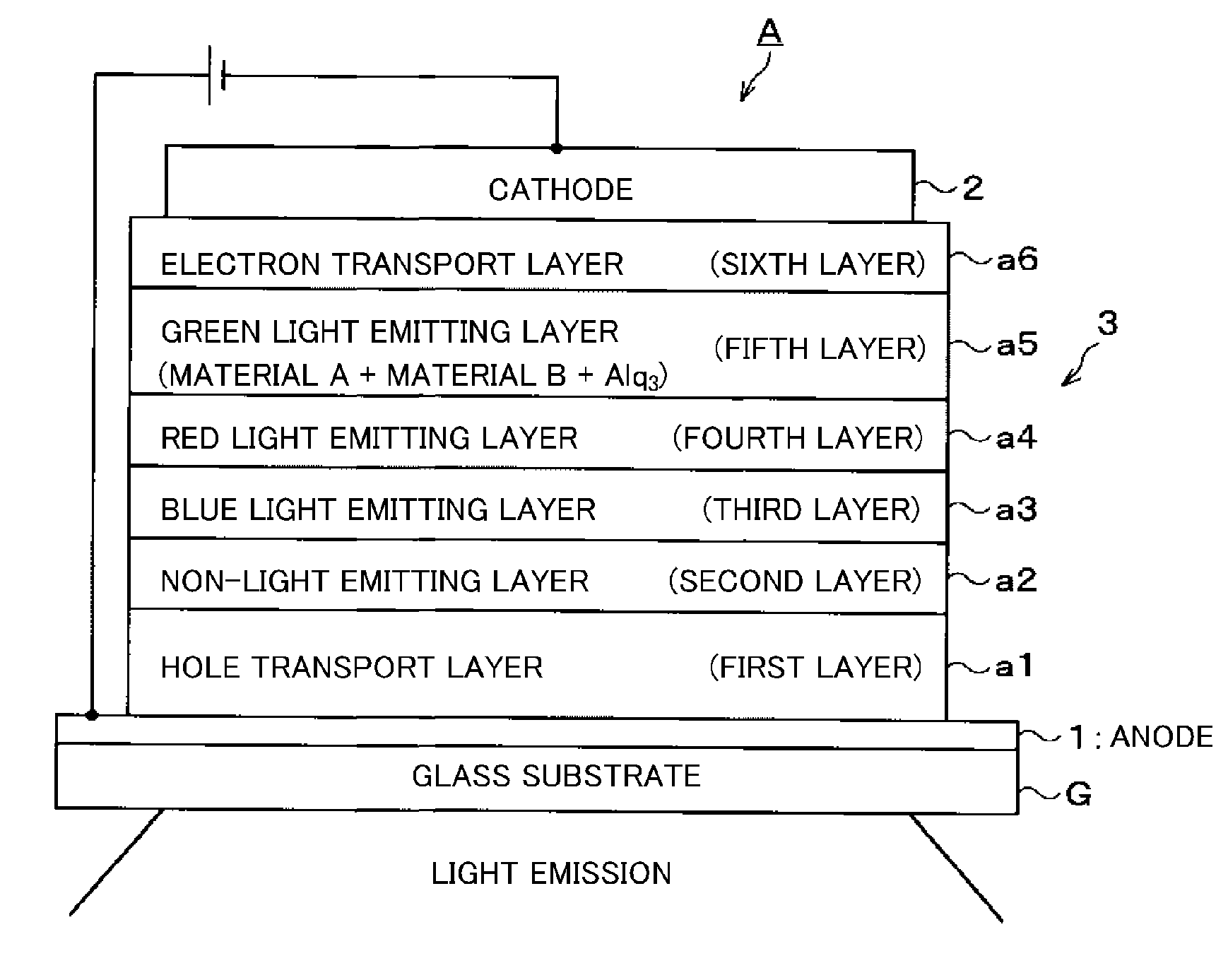
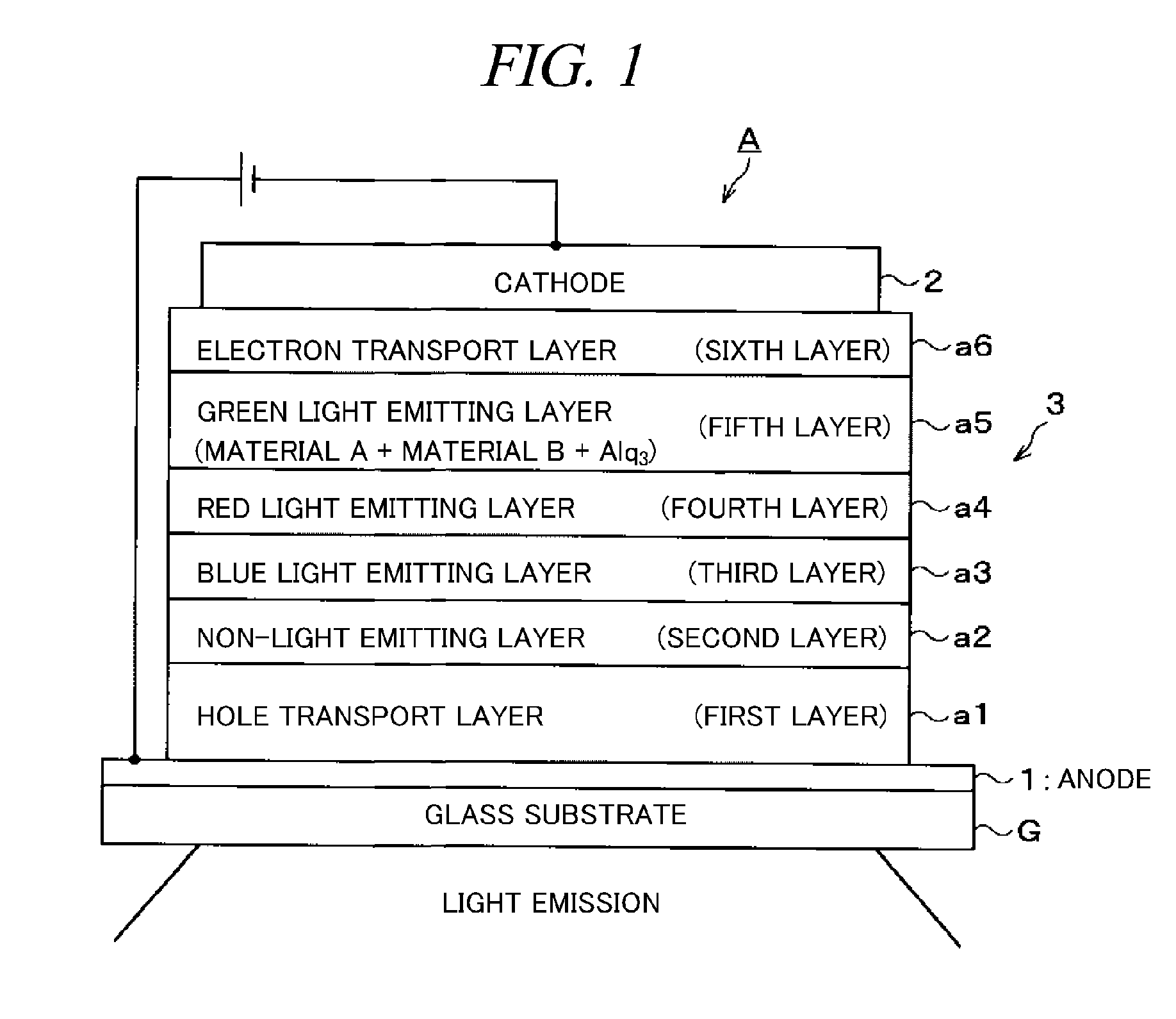
FIELD OF THE INVENTION[0001]The present disclosure relates to a deposition apparatus of organic EL for performing a film forming process by vapor depositing a heated film forming material on a target object to be processed.BACKGROUND OF THE INVENTION[0002]Recently, an organic EL device utilizing electroluminescence (EL) has been developed. Since the organic EL device generates almost no heat, it consumes less power as compared to a cathode-ray tube or the like. Further, since the organic EL device is a self-luminescent device, there are some other advantages, for example, a view angle wider than that of a liquid crystal display (LCD), so that progress thereof in the future is expected.[0003]Most typical structure of this organic EL device includes an anode (positive electrode) layer, a light emitting layer and a cathode (negative electrode) layer stacked sequentially on a glass substrate to form a sandwiched shape. In order to bring out light from the light emitting layer, a transpa...

Claims


Application Information

Patent Timeline
IPC IPC(8): C23C16/54
CPCC23C14/243H01L51/001C23C14/26H10K71/164C23C14/24H05B33/10H10K71/00
Inventor YAGI, YASUSHIWATANABE, SHINGOONO, YUJIKANEKO, HIROSHIHASEGAWA, KOYUKOMINO, MITSUAKI
Owner TOKYO ELECTRON LTD
Why Eureka
Try Eureka