Piston arrangement

Active Publication Date: 2019-10-24
NEWLENOIR
View PDF0 Cites 0 Cited by
  • Summary
  • Abstract
  • Description
  • Claims
  • Application Information

AI Technical Summary

Benefits of technology

[0046]The cylinder may have a central axis, wherein the cylinder axis is not parallel to the axis of rotation of the track relative to the cylinder. The cylinder axis may be offset from the axis of rotation of the track relative to the cylinder by at least 2 degrees or at least 5 degrees or at least 10 degrees or at least 15 degrees or up to 20 degrees. By arranging the cylinder axis at an angle to the axis of rotation of the track the geometry of the piston arrangement and track may be optimized for efficient transfer of power from the pist

Problems solved by technology

A power transfer mechanism including a piston with a follower coupled to an output shaft by a track with a cam surface is larger and may be more difficult to assemble than a conventional power transfer mechanism using a crankshaft and con rod.
As state

Method used


Image

  • Piston arrangement
  • Piston arrangement
  • Piston arrangement

Examples


Example

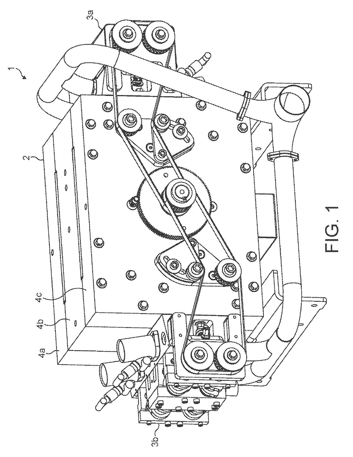
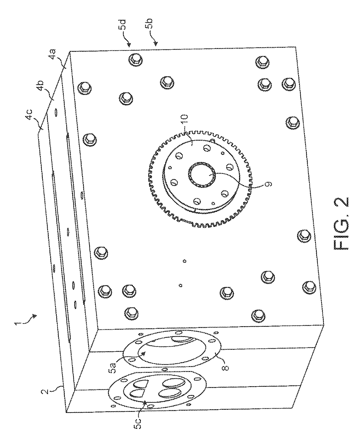
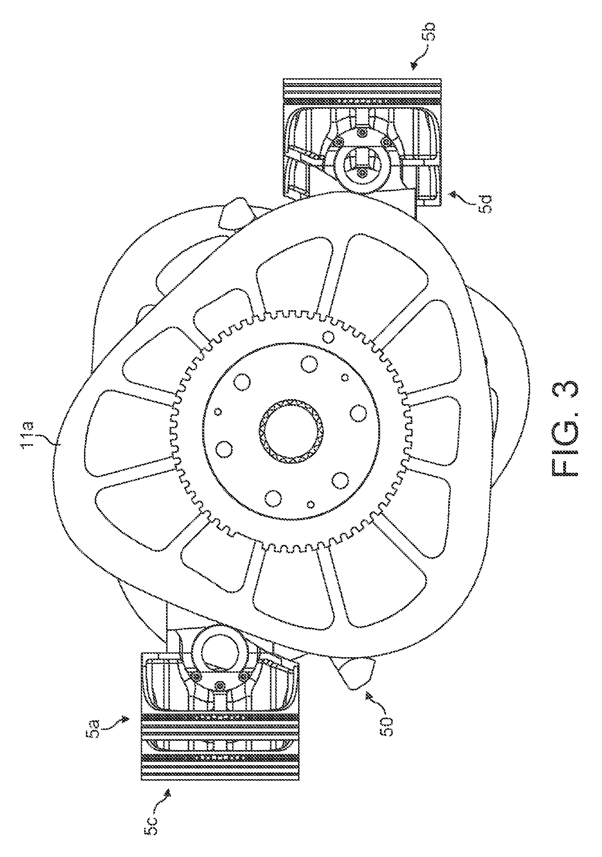
[0090]FIG. 1 shown as internal combustion engine 1 comprising a block assembly 2 and two head assemblies 3a, 3b and an exhaust system. FIG. 2 shows the engine 1 with the head assemblies 3a, 3b and exhaust system omitted. The head assemblies and exhaust system will not be discussed in detail because they do not form part of the invention. The block assembly 2 comprises three casing members 4a, 4b, 4c, in which four piston assemblies 5a, 5b, 5c, 5d are mounted. FIGS. 3 and 4 respectively show end and top views of the engine 1 with the casing members 4a, 4b, 4c, removed so that the piston assemblies 5a, 5b, 5c, 5d are visible. FIGS. 5A, 5B, 6A and 6B show the first piston assembly 5a with the second third and fourth piston assemblies 5b, 5c, 5d omitted for clarity. The structure and functioning of the first piston assembly will be described in detail, although it will be appreciated that the second, third and fourth piston assemblies are structurally and functionally similar to the fir...


PUM

PropertyMeasurementUnit
Shapeaaaaaaaaaa

Abstract

A piston arrangement is provided. The piston assembly includes a track and a piston moveable within a cylinder. The track is rotatable relative to the cylinder about an axis of rotation and has a cam surface and an edge surface extending away from the cam surface. The piston is coupled to the track by a follower running on the cam surface. The cam surface is shaped such that, as the track moves relative to the cylinder, the piston head moves in reciprocating motion within the cylinder along a piston axis in accordance with the path of the cam surface. The piston axis is perpendicular to the track axis of rotation. A stabilizing element is connected to the piston, the stabilizing element extending below the piston head and comprising a contact surface which engages the edge surface of the track.

Description

FIELD[0001]This disclosure relates to piston arrangements, in particular power transfer mechanisms coupling a piston head to a track which controls movement of the piston head.INTRODUCTION[0002]A conventional piston arrangement used, for example, in internal combustion engines comprises a piston head moveable within a cylinder coupled to a crankshaft by a con-rod. In an alternative piston arrangement, a piston head may be coupled to a track having a cam surface, the piston head being provided with one or more cam followers which run along the track to control movement of the piston head. The present invention relates to improvements in the power transfer mechanism coupling a piston head to a track in such an alternative piston arrangement.SUMMARY[0003]A first aspect of the invention provides a piston arrangement including a track and a piston moveable within a cylinder; wherein the track is adapted to rotate relative to the cylinder about an axis of rotation and has a cam surface an...

Claims


Application Information

Patent Timeline
IPC IPC(8): C12N15/113
CPCC12N2320/30C12N2310/315C12N2310/31C12N15/113F01B9/06F01B2009/061F01B3/04F02M59/102F04B1/0531F16J1/10F16J1/20F16M1/02F01M9/101F02B75/40
Inventor BOWEN, RYAN
Owner NEWLENOIR
Why Eureka
Try Eureka