Vacuum bed with base member for three-dimensional printing

Pending Publication Date: 2021-02-11
NORTHWORKS AUTOMATION INC
View PDF0 Cites 2 Cited by
  • Summary
  • Abstract
  • Description
  • Claims
  • Application Information

AI Technical Summary

Benefits of technology

[0014]Upon print completion and termination of the vacuum force, the print surface member can be easily and quickly removed from the base member. The print surface member can be a pliable material, thus readily peeled away from or otherwise removed from the print job.
[0015]In one embodiment, a heating element may be included within or a

Problems solved by technology

Deficiencies exist in the design of 3D printer systems, as well as 3D printing techniques.
If even one hole or channel becomes uncovered, this can break the vacuum seal, allowing the print object to shift.
Current techniques can produce uneven hold-down forces.
This solution is problematic because the cost of creating the vacuum table itself out of this material is prohibitively expensive.

Method used


Image

  • Vacuum bed with base member for three-dimensional printing
  • Vacuum bed with base member for three-dimensional printing
  • Vacuum bed with base member for three-dimensional printing

Examples


Example

[0036]A better understanding of the disclosed technology will be obtained from the following detailed description of the preferred embodiments taken in conjunction with the drawings and the attached claims.

DETAILED DESCRIPTION

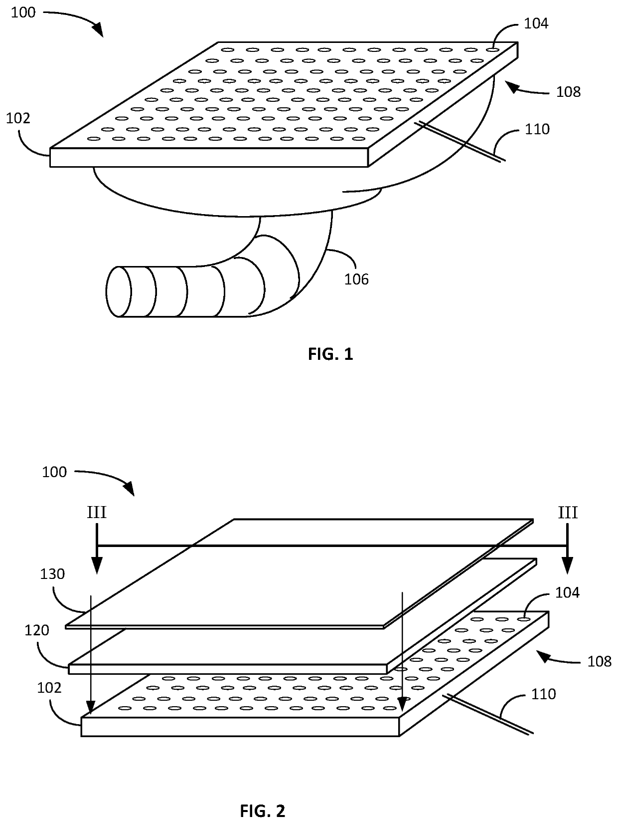
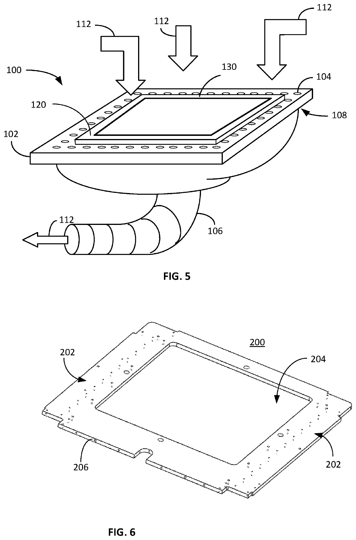
[0037]FIG. 1 illustrates a perspective view of a print bed 100 usable with 3D printing. The print bed 100 includes a vacuum bed 102 having a plurality of air holes 104 therein. A vacuum hose 106 is connected to a bottom side 108 of the bed 102. The print bed 100 further includes a heat element (not visible) disposed within its interior, the heating element including electrical leads 110.

[0038]The print bed 100 may be composed of any suitable material, such as but not limited to metal or plastic. The bed 100 allows for airflow through the holes 104. Varying embodiments allow for different sizing and placement of air holes, including one embodiment may include pin-prick size air holes, whereas other embodiments may include larger holes. Another embodiment may inc...


PUM

PropertyMeasurementUnit
Thicknessaaaaaaaaaa
Thicknessaaaaaaaaaa
Distanceaaaaaaaaaa

Abstract

An improved 3D printer includes an airflow enabled print bed ensuring secure placement of a print base prior to printing. The modular assembly technique provides for improved ease of manufacture and assembly, as well as adjustments of print sizing. The improved printhead includes a heat sink disposed internally therein for improved heat and cooling properties. The printhead itself includes z-axis position detection techniques. The inclusion of VSU insertion techniques in software modeling and printing further improves the print operations by including vertical stability for the print object.

Description

RELATED APPLICATION[0001]The present application relates to and claims priority to, as a continuation-in-part application from, U.S. patent application Ser. No. 15 / 713,519 entitled THREE-DIMENSIONAL PRINTER filed Sep. 22, 2017, which is a continuation-in-part of and claims priority to U.S. Pat. No. 10,189,205 filed Jul. 25, 2017 entitled PRINTER HEAD Z-AXIS ALIGNMENT METHOD AND SYSTEM. The present application additionally relates to and claims priority to, as a continuation application from, U.S. patent application Ser. No. 16 / 865,175 entitled VACUUM SURFACE FOR THREE-DIMENSIONAL PRINTING filed May 1, 2020.COPYRIGHT NOTICE[0002]A portion of the disclosure of this patent document contains material that is subject to copyright protection. The copyright owner has no objection to the facsimile reproduction by anyone of the patent document or the patent disclosure as it appears in the Patent and Trademark Office patent files or records, but otherwise reserves all copyright rights whatsoe...

Claims


Application Information

Patent Timeline
IPC IPC(8): B29C64/245B29C64/295
CPCB29C64/245B33Y30/00B29C64/295B29C64/118B29C64/209B33Y10/00B29C64/393B33Y50/02B22F12/30B22F12/17B22F2999/00B22F12/90B22F10/31B22F10/18Y02P10/25B22F2201/20C22C1/08
Inventor CISCON, LAWRENCEWISE, JAMES DHYATT, JOHN
Owner NORTHWORKS AUTOMATION INC
Why Eureka
Try Eureka