Buffer device and method for buffering containers

Pending Publication Date: 2022-06-09
KRONES AG
View PDF0 Cites 0 Cited by
  • Summary
  • Abstract
  • Description
  • Claims
  • Application Information

AI Technical Summary

Benefits of technology

[0046]Conversion from single-row transportation to multiple-row transportation is possible with this embodiment in a selective manner without the need for robotic arms or transf

Problems solved by technology

The known buffer systems are not very flexible with regard to the transportation of the containers and the buffer capacity and the path to be traveled by the containers can hardly also be adapted to requirements

Method used


Image

  • Buffer device and method for buffering containers
  • Buffer device and method for buffering containers
  • Buffer device and method for buffering containers

Examples


Embodiment Construction

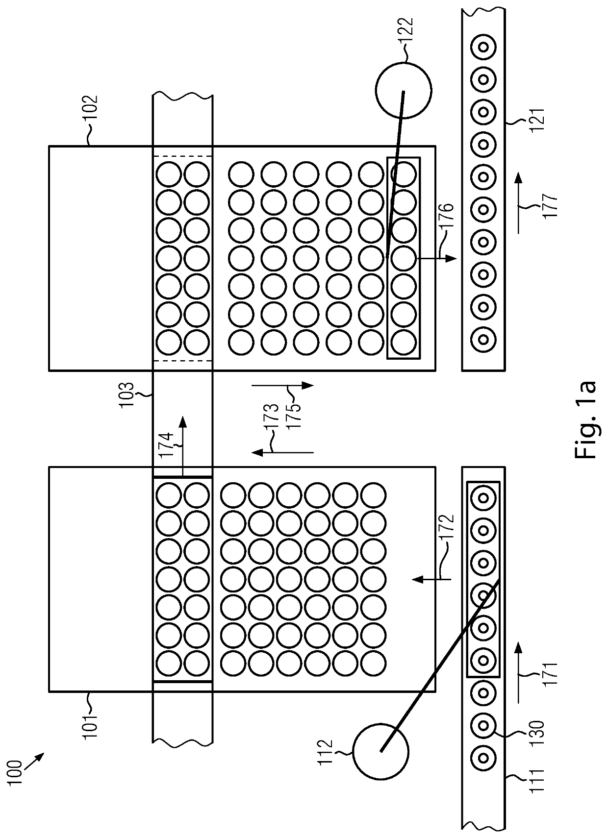
[0054]FIG. 1a shows an embodiment of a buffer system 100 according to the disclosure. Buffer system 100 is configured to buffer (i.e. to temporarily store or to buffer store) containers 130, such as bottles, cans, tubes or other containers. In an embodiment, buffering there takes place between two machines which can be configured to treat the respective containers. For example, a first container treatment machine (for example, a printing machine that applies a print image onto each container) can be arranged upstream of buffer device 100 and a second container treatment machine, such as a packer that packs containers to form bundles, can be arranged downstream of the buffer device. The containers are transported in transport devices from the first container treatment machine to the second container treatment machine. They can be, for example, conveyor belts or the like.

[0055]Neither the container treatment machines employed nor the type of transportation between the container treatm...


PUM


Abstract

Buffer device for buffering containers, with an inlet, an inlet manipulator, a first buffer system, a transposition device, a second buffer system, an outlet manipulator, and an outlet, where containers can be transferred by the inlet manipulator from the inlet to the first buffer system and can be transported along a first direction in the first buffer system, where the transposition device can transfer containers from the first buffer system to the second buffer system, and the containers can be transported in the second buffer system along a second direction that is opposite to the first direction, and the containers can be removed from the second buffer system by the outlet manipulator and fed to the outlet, where the buffer capacity of the buffer device is adjustable.

Description

TECHNICAL FIELD[0001]The present disclosure relates to a buffer device for buffering containers as well as to a method for buffering containers with a buffer device.BACKGROUND AND SUMMARY[0002]Devices for buffering containers and corresponding methods are known from prior art.[0003]A buffer device is already known from US 2015 / 037126 in which a robot can receive a group of containers from a multiple-row flow of containers and feed them to a buffer region which extends in a direction that is perpendicular to the direction of transport of the containers.[0004]It is known from EP 2 920 093 B1 to provide a buffer region between two container transport devices arranged consecutively in the direction of transport of the containers. The containers are examined by the first transport device for the buffer region and by the buffer region for the second transport device, so that the buffer region is always completely traversed by containers.[0005]The known buffer systems are not very flexible...

Claims


Application Information

Patent Timeline
IPC IPC(8): B65G47/51B65G47/08
CPCB65G47/5113B65G47/088B65G47/256B65G47/5109
Inventor SCHUESSLBURNER, HELMUTSENN, KONRAD
Owner KRONES AG
Why Eureka
Try Eureka