Medium supply device and image forming apparatus

a technology of image forming apparatus and supply device, which is applied in the direction of article separation, thin material handling, instruments, etc., can solve the problems of easy paper jams and excessive braking force, and achieve the effect of reducing the braking force of the medium separation mechanism, reducing the occurrence of paper jams, and reducing the braking for

Active Publication Date: 2017-12-28
OKI DATA CORP
View PDF3 Cites 2 Cited by
  • Summary
  • Abstract
  • Description
  • Claims
  • Application Information

AI Technical Summary

Benefits of technology

[0005]It is an object of the present invention to provide a medium supply device and an image forming apparatus that can reduce a braking force of a medium separating mechanism and therefore can reduce occurrence of paper jams only by attaching the medium supply device to an image forming apparatus body.
[0006]A medium supply device according to an aspect of the present invention is configured to be attached to an image forming apparatus body including a medium separating mechanism, and the medium supply device includes: a medium conveying mechanism that supplies a recording medium from stacked recording media to a predetermined position; and a first mechanism that reduces a braking force generated in the medium separating mechanism.
[0007]According to the present invention, a braking force of the medium separating mechanism can be reduced so that occurrence of paper jams can be reduced by attaching the medium supply device to the image forming apparatus body.

Problems solved by technology

In the case of attaching the medium supply device to the MPT section to supply the special media (e.g., envelopes), however, an excessive braking force (which is a force acting in a direction opposite to a conveying direction) might be applied from the medium separating mechanism to the special media in some cases.
In such cases, flaps of the envelopes as the special media are lifted or the like occur, and therefore paper jams easily occur.

Method used


Image

  • Medium supply device and image forming apparatus
  • Medium supply device and image forming apparatus
  • Medium supply device and image forming apparatus

Examples


first embodiment

First Embodiment

Configuration

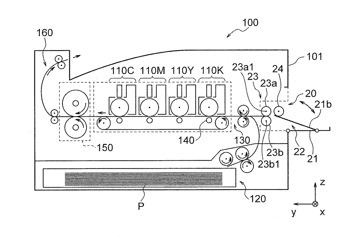
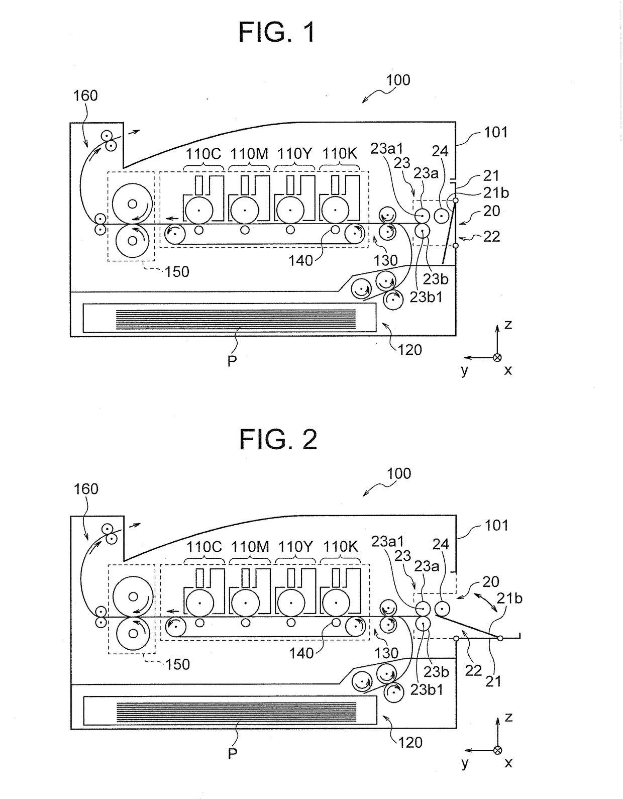
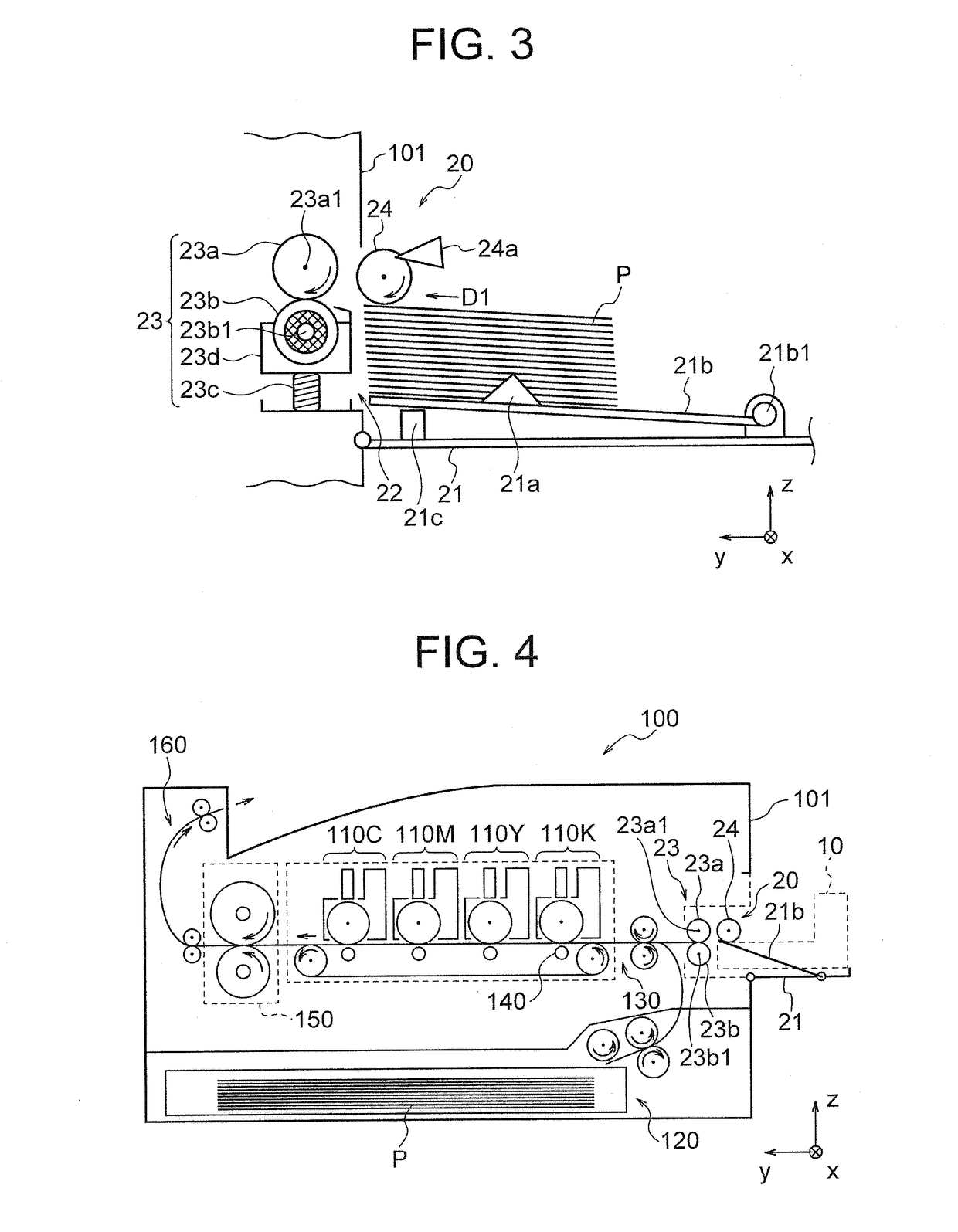
[0022]First, with reference to FIGS. 1 through 3, an image forming apparatus 100 including an MPT section 20 to which a medium supply device according to the first embodiment can be attached will be described. FIG. 1 is a cross-sectional view illustrating a schematic configuration of the image forming apparatus 100 including the MPT section 20 to which the medium supply device according to the first embodiment can be attached (when an MPT tray 21 of the MPT section 20 is closed). FIG. 2 is a cross-sectional view illustrating a schematic configuration of the image forming apparatus 100 including the MPT section 20 to which the medium supply device according to the first embodiment can be attached (when the MPT tray 21 of the MPT section 20 is open). Further, FIG. 3 is a cross-sectional view schematically illustrating a state of a medium separating mechanism (e.g., friction separating mechanism) 23 and a pickup roller 24 in a case where recording media (...

second embodiment

Second Embodiment

[0039]In the first embodiment described above, when the medium supply device 10 is attached to the image forming apparatus 100, the medium conveying mechanism 12 of the medium supply device 10 presses the pickup roller 24 to change the position of the pickup roller 24 in the z direction, and the position sensor 24a apparently detects the state indicating the presence of a recording medium by detecting the position of the pickup roller 24 in the z direction. On the other hand, in the second embodiment of the present invention, the elevation mechanism 21c that elevates and lowers a sheet receiver 21b of the MPT tray 21 in the z direction may be used so that a medium conveying mechanism 12 rotates about a support shaft of a roller 15c (in a direction D2 in FIG. 7) and, thereby, the position of a pickup roller 24 in the z direction is changed.

[0040]FIG. 7 is a cross-sectional view illustrating a schematic configuration of a medium supply device 10a according to the sec...

third embodiment

Third Embodiment

[0042]In the first and second embodiments, the pressing mechanism 13 is provided in the frame unit (first frame unit) 11. On the other hand, in the third embodiment of the present invention, the medium conveying mechanism 12 is provided in a frame unit (first frame unit) 11, and the pressing mechanism 13 is provided in a conveyance guide unit (second frame unit) 31.

[0043]FIGS. 8A and 8B are cross-sectional views illustrating a schematic configuration of a medium supply device 10b according to the third embodiment (in a state of not being attached to the MPT section 20). In FIGS. 8A and 8B, constitutional elements that are the same as or correspond to those shown in FIG. 5 (first embodiment) are designated by the same reference characters as those shown in FIG. 5. FIG. 9 is a cross-sectional view illustrating a schematic configuration of the medium supply device 10b according to the third embodiment (in a state of being attached to the MPT section 20). In FIG. 9, con...


PUM


Abstract

Provided is an apparatus that can reduce a braking force of a medium separating mechanism to thereby reduce occurrence of paper jams only by attaching a medium supply device to an image forming apparatus body. The medium supply device is configured to be attached to an image forming apparatus body including a medium separating mechanism, and includes a medium conveying mechanism that supplies a recording medium from stacked recording media to a predetermined position, and first mechanism that reduces a braking force generated in the medium separating mechanism.

Description

BACKGROUND OF THE INVENTION1. Field of the Invention[0001]The present invention relates to a medium supply device configured to be attached to an image forming apparatus and an image forming apparatus including a medium supply device.2. Description of the Related Art[0002]Conventionally, an image forming apparatus including a multi-purpose tray (MPT) section has been widely used (see, for example, Japanese Patent Application Publication No. 2015-127250). A medium to be conveyed from the MPT section to the image forming apparatus body (also referred to as an “apparatus body”) is separated by a medium separating mechanism.[0003]In some apparatuses, the MPT section has a structure that enables removable attachment (installation) of a medium supply device (paper feed device) on which recording media (special media) having special shapes such as envelopes are stacked. The attachment (installation) of the medium supply device enables these apparatuses to perform continuous printing on the...

Claims


Application Information

Patent Timeline
Patent Type & Authority Applications(United States)
IPC IPC(8): B41J11/00B41J13/00B41J13/10B41J11/22B41J13/14
CPCB41J11/006B41J11/0045B41J11/22B41J13/009B41J13/14B41J13/106B41J13/103B65H1/04B65H1/266B65H3/52B65H2405/313B65H2405/361B65H2407/21B65H2701/1916G03G15/6502
Inventor YUASA, HIROSHI
Owner OKI DATA CORP
Why Eureka
Try Eureka