Vibration wave motor and lens driving apparatus

a technology of vibration wave and driving apparatus, which is applied in the direction of mechanical vibration separation, mountings, instruments, etc., can solve the problems of increasing the size of the structure in the relative movement direction (longitudinal direction), increasing the sliding resistance, and increasing the reaction force of the pressurizing spring, so as to reduce the size of the vibrator and increase the size of the pressurizing member. , the effect of increasing the size of the pressurizing member

Active Publication Date: 2017-12-28
CANON KK
View PDF6 Cites 11 Cited by
  • Summary
  • Abstract
  • Description
  • Claims
  • Application Information

AI Technical Summary

Benefits of technology

[0009]According to the present invention, the provision of the buffering member between the vibrator and the holding member enables the holding member to hold the vibrator through the buffering member, so that the size of the pressurizing member is not increased more than necessary.
[0010]Further, since the holding member holds the vibrator by sandwiching the vibrator and the buffering member, a reduction in the size of the vibrator in the relative movement direction can be achieved without increasing the size of the pressurizing member more than necessary.

Problems solved by technology

This causes a problem that the size of the structure in the relative movement direction (longitudinal direction) is increased by the amount corresponding to the holding unit.
However, if a sufficient pressurizing force is obtained without changing a spring constant of a pressurizing spring serving as the pressurizing member, problems such as an increase in the size of the pressurizing member and an increase in sliding resistance along with an increase in reaction force of the pressurizing spring are raised.

Method used


Image

  • Vibration wave motor and lens driving apparatus
  • Vibration wave motor and lens driving apparatus
  • Vibration wave motor and lens driving apparatus

Examples


first embodiment

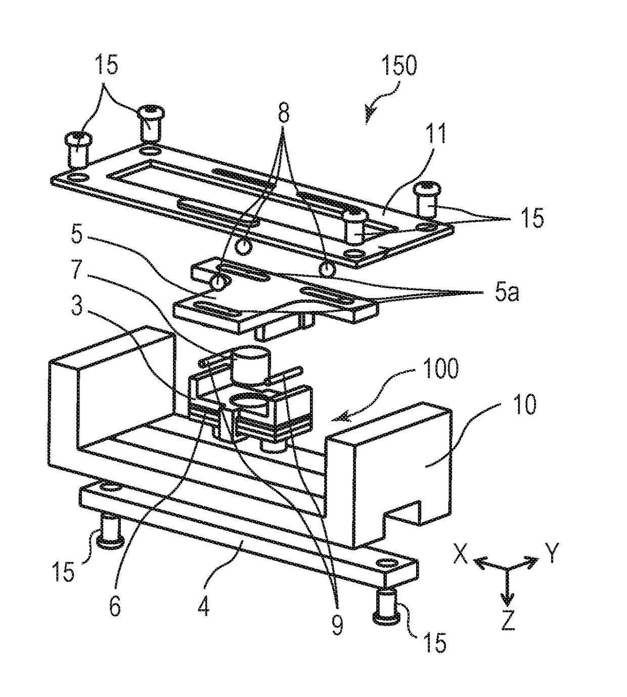
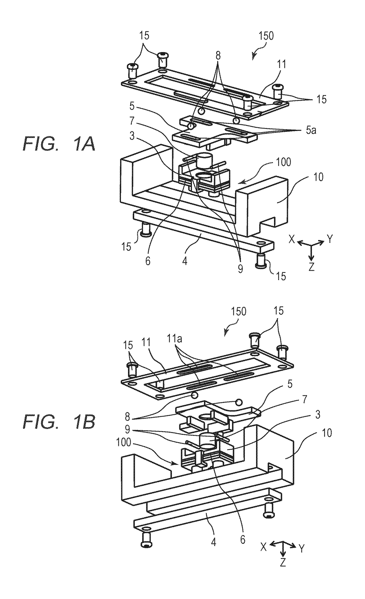
[0028]A first embodiment of the present invention will be described below. FIGS. 1A and 1B are exploded perspective views each illustrating a vibration wave motor 150 according to the first embodiment, and each of the perspective views is viewed from different angles. The vibrator 100 includes an elastic body 1 and a piezoelectric element 2. A detailed structure of the vibration wave motor 150 is described later. The structure of the vibrator 100 will now be described.

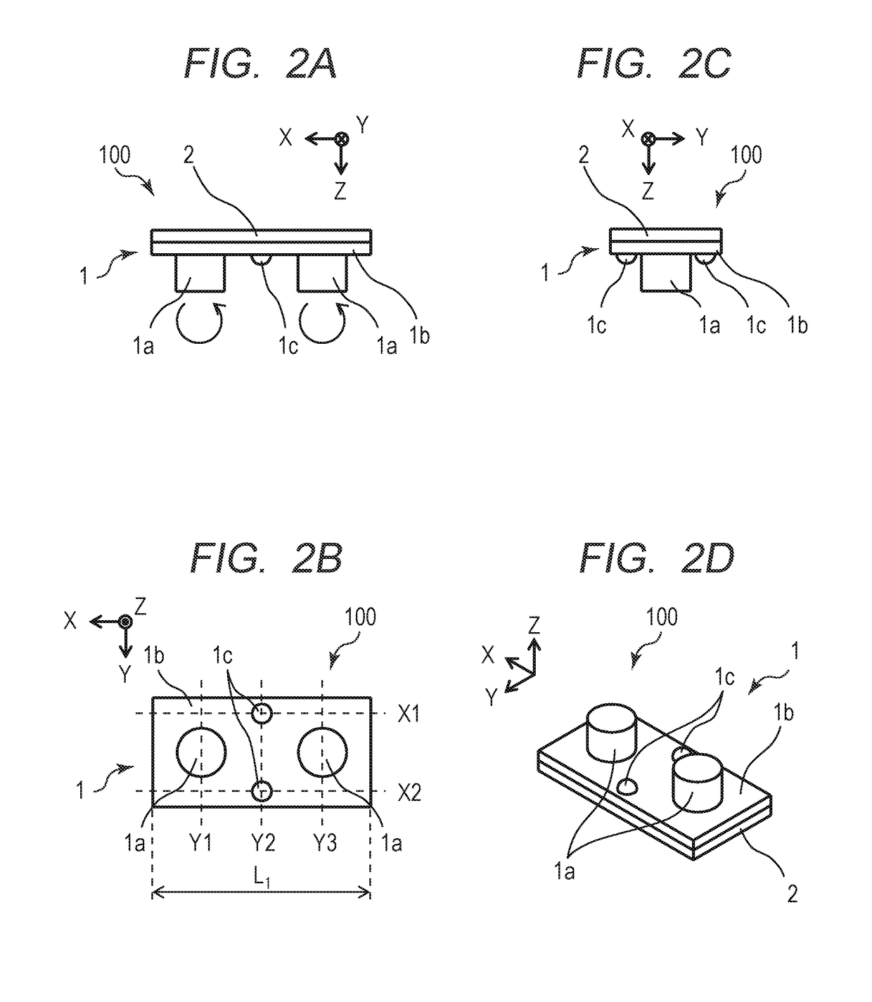
[0029]FIGS. 2A to 2D are diagrams each illustrating the vibrator 100 according to the first embodiment. FIG. 2A is a front view of the vibrator 100. FIG. 2B is a bottom view of the vibrator 100. FIG. 2C is a side view of the vibrator 100. FIG. 2D is a perspective view of the vibrator 100. The elastic body 1 serving as a vibrating plate includes a rectangular flat plate part 1b and protrusions 1a provided on the flat plate part 1b. The vibrator 100 has a structure in which the piezoelectric element 2 that vibrates at a ...

second embodiment

[0063]Next, a vibration wave motor 250 according to a second embodiment of the present invention will be described. The first embodiment illustrates an example in which the pressurizing force F1a by the pressurizing member 7 and the holding reaction force F2′ by the holding member 3 are applied at the same location. The second embodiment differs from the first embodiment in that the pressurizing force F1a by a pressurizing member 207 and the holding reaction force F2′ by a holding member 203 are applied at different locations. Descriptions of components of the second embodiment that are the same as those of the first embodiment are omitted, and only components of the second embodiment that are different from those of the first embodiment will be described.

[0064]FIGS. 7A to 7E are diagrams each illustrating a vibrator 200 and a method for holding the vibrator 200 according to the second embodiment. FIGS. 7A to 7D correspond to FIGS. 3A to 3D, respectively. FIG. 7A is a bottom view of...

third embodiment

[0076]A vibration wave motor 350 according to a third embodiment of the present invention will be described below. The second embodiment illustrates an example in which the pressurizing force F1b of the pressurizing member 207 is applied to the buffering member 206 at two locations on the pressurizing surfaces 212b. The third embodiment differs from the second embodiment in that a pressurizing force of a pressurizing member 307 is applied to a buffering member 306 at one location on the pressurizing surface 312b. Descriptions of components of the third embodiment that are the same as those of the second embodiment are omitted, and only components of the third embodiment that are different from those of the second embodiment will be described.

[0077]FIGS. 10A to 10D are diagrams each illustrating a vibrator 300 and a method for holding the vibrator 300 according to the third embodiment, and correspond to FIGS. 3A to 3D, respectively. FIGS. 11A to 11C are diagrams each illustrating the...


PUM


Abstract

Provided is a vibration wave motor including: a vibrator; a pressurizing member configured to pressurize the vibrator against a friction member; a holding member configured to hold the vibrator; and a buffering member provided between the vibrator and the holding member. The vibrator and the friction member are moved relatively to each other in a relative movement direction by vibration of the vibrator, and the holding member holds the vibrator in such a manner that an extending part extending in a pressurizing direction of the pressurizing member sandwiches the vibrator and the buffering member.

Description

BACKGROUND OF THE INVENTIONField of the Invention[0001]The present invention relates to a vibration wave motor, and more particularly, to a linear vibration wave motor including a plate-shaped elastic body, and a lens driving apparatus using the linear vibration wave motor.Description of the Related Art[0002]Heretofore, vibration wave motors characterized by enabling a reduction in size and weight, high-speed driving, and silent driving have been employed as, for example, actuators for a lens barrel of an imaging device. Among these motors, a vibration wave motor for linear driving as described below is disclosed in Japanese Patent Application Laid-Open No. 2015-126692.[0003]The vibration wave motor disclosed in Japanese Patent Application Laid-Open No. 2015-126692 includes a vibrator including a piezoelectric element and an elastic body, a friction member that comes into frictional contact with the vibrator, and a holding member that holds the vibrator. A high-frequency vibration i...

Claims


Application Information

Patent Timeline
Patent Type & Authority Applications(United States)
IPC IPC(8): G02B7/02B06B1/06H02N2/00H02N2/02
CPCG02B7/02H02N2/0065B06B1/06H02N2/0055H02N2/026B06B1/0644B06B1/12H02N2/006G02B7/005G02B7/023H02N2/0015H02N2/0025
Inventor NINOMIYA, SHUNSUKE
Owner CANON KK
Why Eureka
Try Eureka