Containment Internal Passive Heat Removal System

a technology of containment and passive heat removal, which is applied in the field of nuclear energy, can solve problems such as potent water hammer in the system, and achieve the effects of improving energy efficiency and performance of heat exchangers, reducing the non-uniformity of coolant flow distribution, and improving coolant distribution

Active Publication Date: 2017-12-28
SCI RES & DESIGN INST FOR ENERGY TECH ATOMPROEKT JSC ATOMPROEKT
View PDF0 Cites 5 Cited by
  • Summary
  • Abstract
  • Description
  • Claims
  • Application Information

AI Technical Summary

Benefits of technology

[0041]The correlation of the section length and bore of the heat exchanger headers is selected so as to minimize the non-uniformity of coolant flow distribution among the heat exchanger tubes, i.e. to reduce the so-called “header effect”. The uniform distribution of flow in the tubing is one of the main conditions for improved energy efficiency and performance of heat exchangers. One of the methods used to improve coolant distribution among the header heat exchanger channels is pressure loss reduction of the medium flow in the header. This is achiev...

Problems solved by technology

The disadvantage of the said device...

Method used


Image

  • Containment Internal Passive Heat Removal System
  • Containment Internal Passive Heat Removal System
  • Containment Internal Passive Heat Removal System

Examples


Embodiment Construction

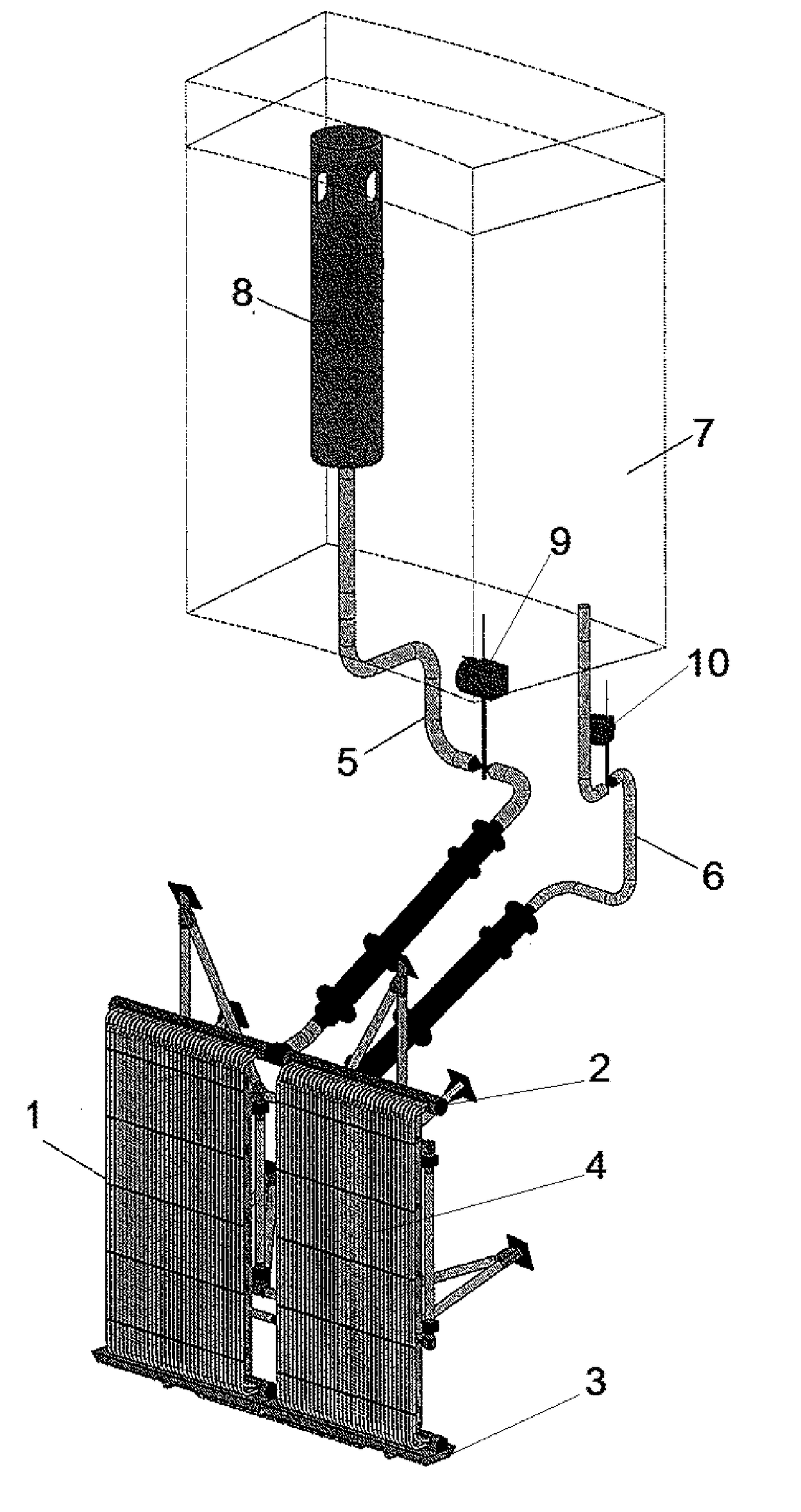
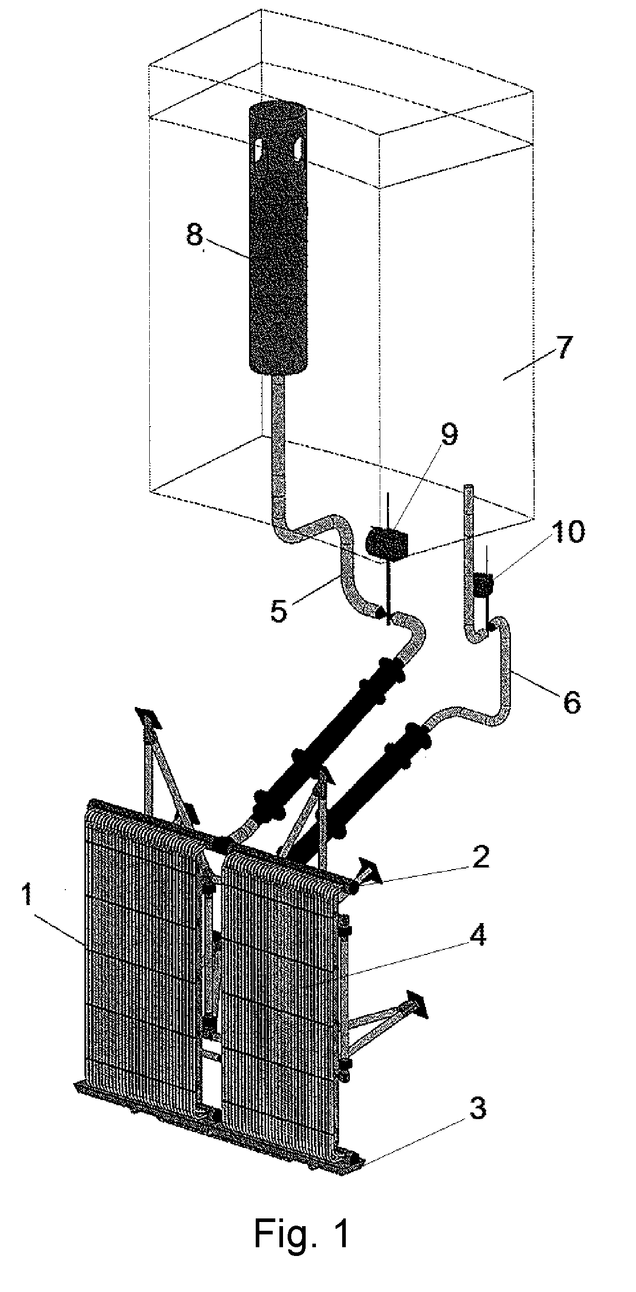
[0046]The claimed system is a combination of cooling water circulation circuits. In the preferable embodiment of the invention, the claimed system consists of four completely independent channels, each comprising four such circulation circuits.

[0047]The circulation circuit (FIG. 1) comprises a heat exchanger (1) located inside the containment (under the dome) and including an upper header (2) and a lower header (3) interconnected by heat-exchange tubes (4) forming a single-row vertical heat-exchange bundle. A riser pipeline (5) and a downtake pipeline (6) are connected to the heat exchanger (1). A cooling water supply tank (emergency heat removal tank (EHRT)) (7) connected to the downtake pipeline (6) is located above the heat exchanger outside the containment. A steam relief valve (8) connected to the riser pipeline (5) is located in the cooling water supply tank (7) and connected to the same hydraulically. The steam relief valve (8) is designed for elimination of condensate-induce...


PUM


Abstract

The invention relates to the nuclear energy field, including pressurized water reactor containment internal passive heat removal systems. The invention increases heat removal efficiency, flow stability in the circuit, and system reliability. The system has at least one cooling water circulation circuit comprising a heat exchanger inside the containment and including an upper and lower header interconnected by heat-exchange tubes, a riser pipeline and a downtake pipeline connected to the heat exchanger, a cooling water supply tank above the heat exchanger outside the containment and connected to the downtake pipeline, a steam relief valve connected to the riser pipeline and located in the water supply tank and hydraulically connected to the latter. The upper and lower header of the heat exchanger are divided into heat exchange tube sections on the assumption that: L/D≦20, L being the header section length, D being the header bore.

Description

CROSS-REFERENCE TO RELATED APPLICATIONS[0001]The current application is a US 371 National Stage application from PCT / RU2015 / 000784 filed Nov. 16, 2015, which claims the benefit of priority application RU2014148910 filed Dec. 4, 2014, the disclosures of which are incorporated herein by reference in their entirety.BACKGROUND OF THE INVENTIONTechnical Field[0002]The invention relates generally to the nuclear energy field, and more particularly to pressurized water reactor containment internal passive heat removal systems (C PHRS), and is designed for reactor containment cooling by natural circulation of the cooling liquid (water) in the system circuit.Description of Related Art[0003]According to the background of the invention, there are numerous designs of reactor containment heat removal systems based on natural heat circulation.[0004]Russian patent RU2125744, G21C15 / 18 dated Jan. 27, 1999 discloses a system for passive heat removal from the nuclear reactor containment structure inte...

Claims


Application Information

Patent Timeline
IPC IPC(8): G21C15/18G21C1/02G21C13/036G21C9/004G21C15/14G21D3/04
CPCG21C15/18G21C9/004G21D3/04G21C13/036G21C15/14G21C1/028G21D3/02Y02E30/30F28D3/00F28C3/04F28D1/00
Inventor BEZLEPKIN, VLADIMIR VICTOROVICHSEMASHKO, SERGEY EVGENIVICHIVKOV, IGOR MIHAYLOVICHALEKSEEV, SERGEY BORISOVICHVARDANIDZE, TEYMURAZ GEORGIEVICHPETROV, YURIY YURIEVICHSOLODOVNIKOV, ALEKSANDER SERGEEVICHKRYLOV, YURIY VLADIMIROVICH
Owner SCI RES & DESIGN INST FOR ENERGY TECH ATOMPROEKT JSC ATOMPROEKT
Why Eureka
Try Eureka