Railless tugger train

a technology of rails and trains, applied in the direction of vehicles, steering parts, transportation and packaging, etc., can solve the problems of high production costs, and achieve the effect of simplifying design layout and configuration

a technology of rails and trains, applied in the direction of vehicles, steering parts, transportation and packaging, etc., can solve the problems of high production costs, and achieve the effect of simplifying design layout and configuration

US20180001947A1Inactive Publication Date: 2018-01-04HELMUT SCHMIDT UNIV UNIV DER BUNDESWEHR HAMBURG

Image

  • Railless tugger train
  • Railless tugger train
  • Railless tugger train

Examples


Embodiment Construction

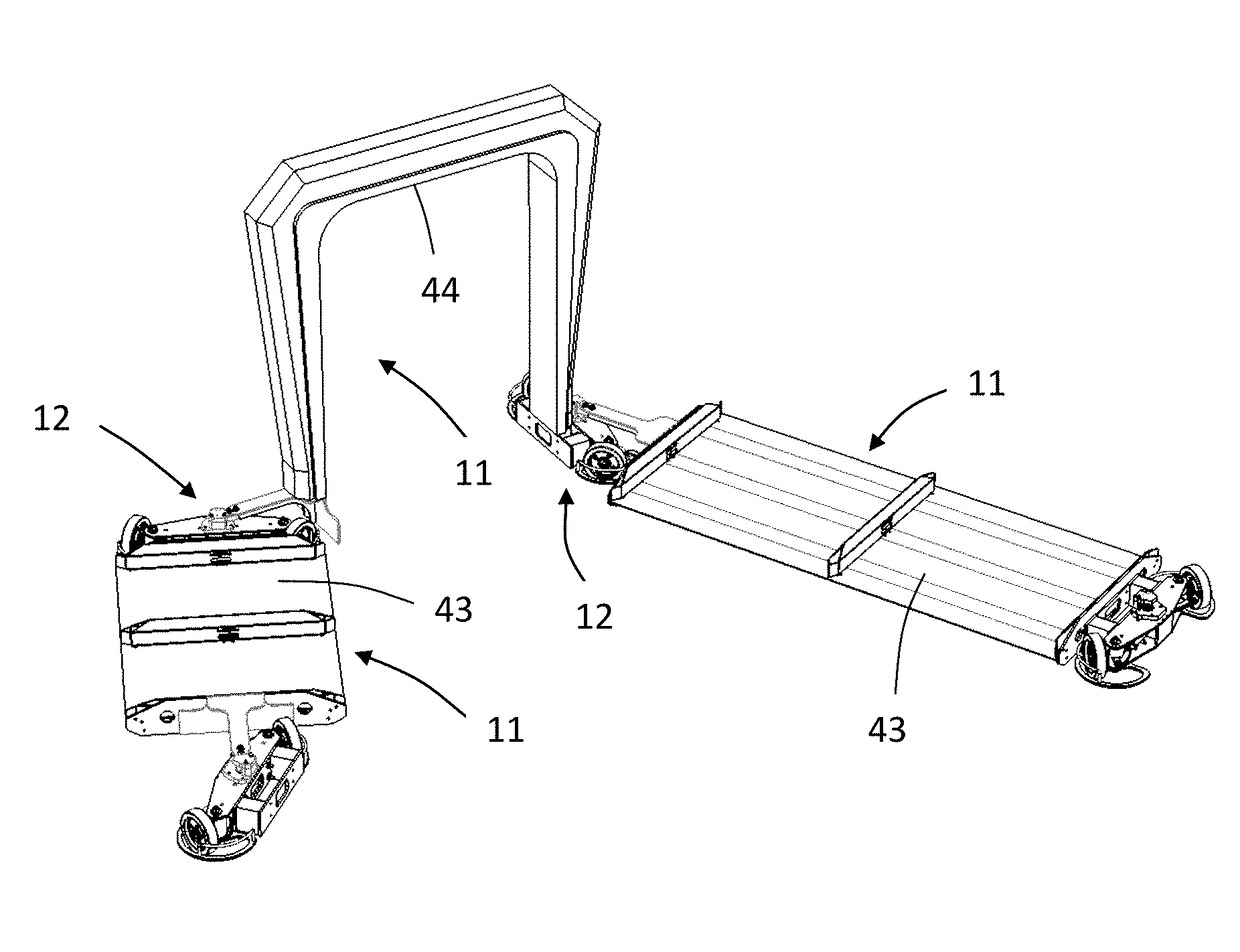
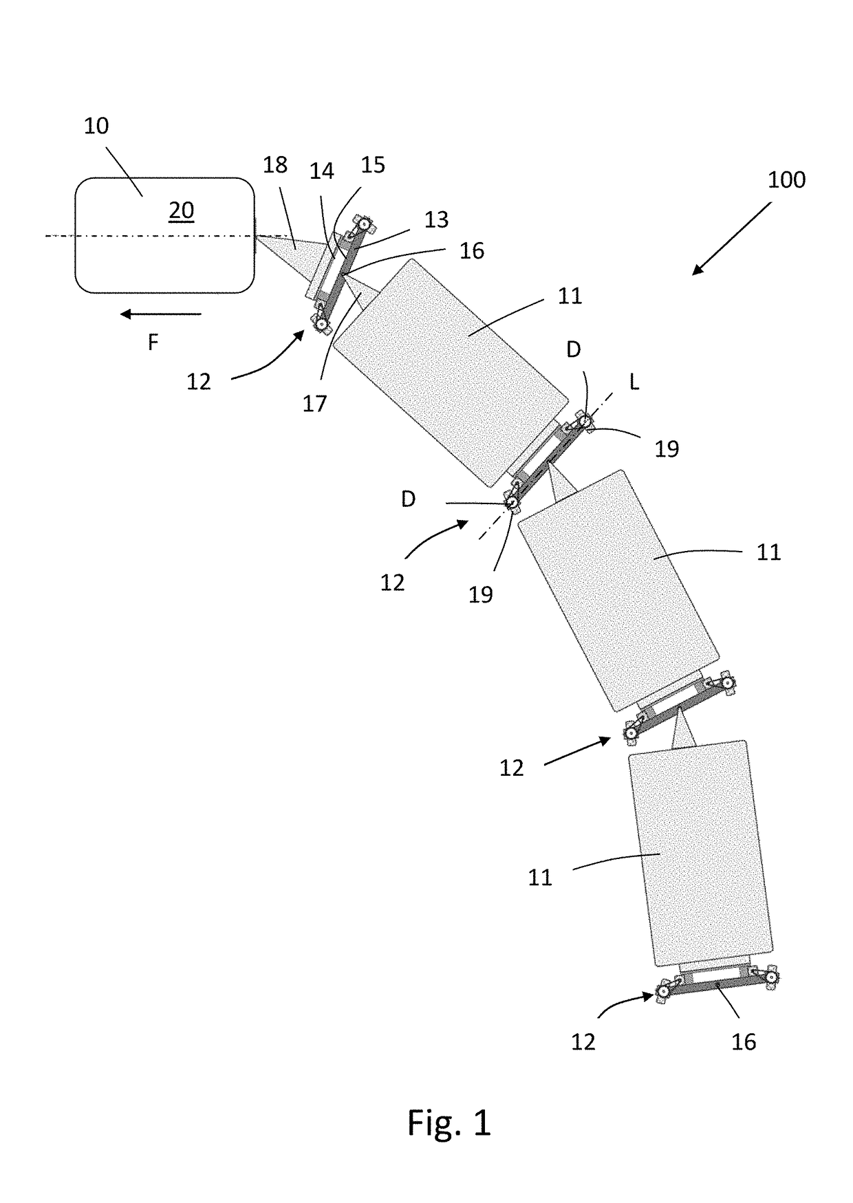
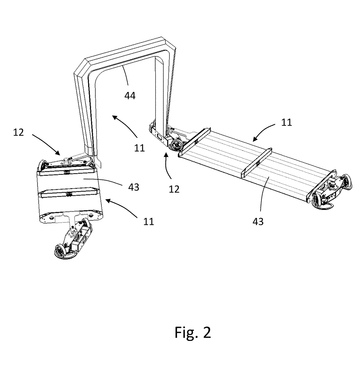
[0042]FIG. 1 schematically shows a railless tugger train 100 according to the invention. The railless tugger train has a train module 10, several transportation modules 11 arranged behind one another and several axis modules 12, wherein one axis module 12 each is arranged between two transportation modules 12 arranged behind each other and between the train module 10 and the first—in driving direction F—transportation module 11. Further, an axis module 12 is assigned also to the—in driving direction F—last transportation module 11 as completion of the tugger train 100.

[0043]Each axis module 12 has a fixedly configured axis beam 13, which is configured in the form of a rod or a beam.

[0044]A first mounting device 14 is configured in the form of a stiff mounting of the train module 10 or a transportation module 11 at each axis beam 13, wherein this first mounting device 14 is preferably configured at the—in driving direction F—forward longitudinal side 15 of the axis beam 13. The train...


PUM


Abstract

A railless tugger train (100) includes a train module (10), at least one transportation module and at least two axis modules, wherein each axis module has a stiffly configured axis beam, at which a first mounting device is configured in the form of a stiff mounting of the train module or a transportation module and at which a second mounting device is configured for an articulated connection of a transportation module. At least two wheels (19) are mounted at the axis beam in such a way that the wheels are each rotatable around a rotation axis (D) which is configured vertical to the longitudinal axis (L) of the axis beam.

Description

[0001]The present invention relates to a railless tugger train comprising a train module, at least one transportation module and at least two axis modules.PRIOR ART[0002]Railless tugger trains can be used in particular as ground conveyors for an in-house transportation. Such a railless tugger train is for example known from EP 2 944 549 A2. The tugger train described there has several transportation modules arranged behind one another, which are pulled by a train module. An axis module is arranged between the train module and the—in driving direction—first transportation module as well as between each of the then following transportation modules. The axis modules each comprise a wheel axle, at which two wheels each are arranged. For connecting the axis modules with the transportation modules or with the train module, two cantilever arms, which are connected to a transportation module or a train module, are arranged at each of the axis modules. These cantilever arms are connected to ...

Claims


Application Information

Patent Timeline
04 Jan 2018
Publication
US20180001947A1
IPC
B62D59/04; B62D13/04; B62D6/00; B62D53/00; B60S9/205
CPC
B62D59/04; B62D53/005; B60S9/205; B62D6/002; B62D13/04; B62D13/00; B62D13/005
Inventors
BRUNS, RAINER; ULRICH, STEPHAN