Power control apparatus for sub-module of mmc converter

Active Publication Date: 2018-01-04
HYOSUNG HEAVY IND CORP
View PDF1 Cites 0 Cited by
  • Summary
  • Abstract
  • Description
  • Claims
  • Application Information

AI Technical Summary

Benefits of technology

[0028]According to the present invention, loss occurring in current-limiting resistors and a Zener diode constituting the power control apparatus for sub-modules in an MMC may be minimized, and the generation of heat may be prevented, and thus there is no need to attach an additional device, such as a heat

Problems solved by technology

Since loss occurring during the operation of sub-modules negatively influences the efficient operation of the sub-modules, efforts to minimize such loss have been continuously made.
However, the conventional power control apparatus 20 is problematic in that loss occurs due to heat generated in the resistors R1 and R2 for current limiting, and such heat generation may negatively influence the overall operation of the power control apparatus because it is closely related to the reliability of elements.
Thus, there is inconvenience in that a heat dissipation plate for preventing heat generation must be separately attached.
For this reason, if current-limiting resistors R1 and R2 are selected so that the

Method used


Image

  • Power control apparatus for sub-module of mmc converter
  • Power control apparatus for sub-module of mmc converter
  • Power control apparatus for sub-module of mmc converter

Examples


Example

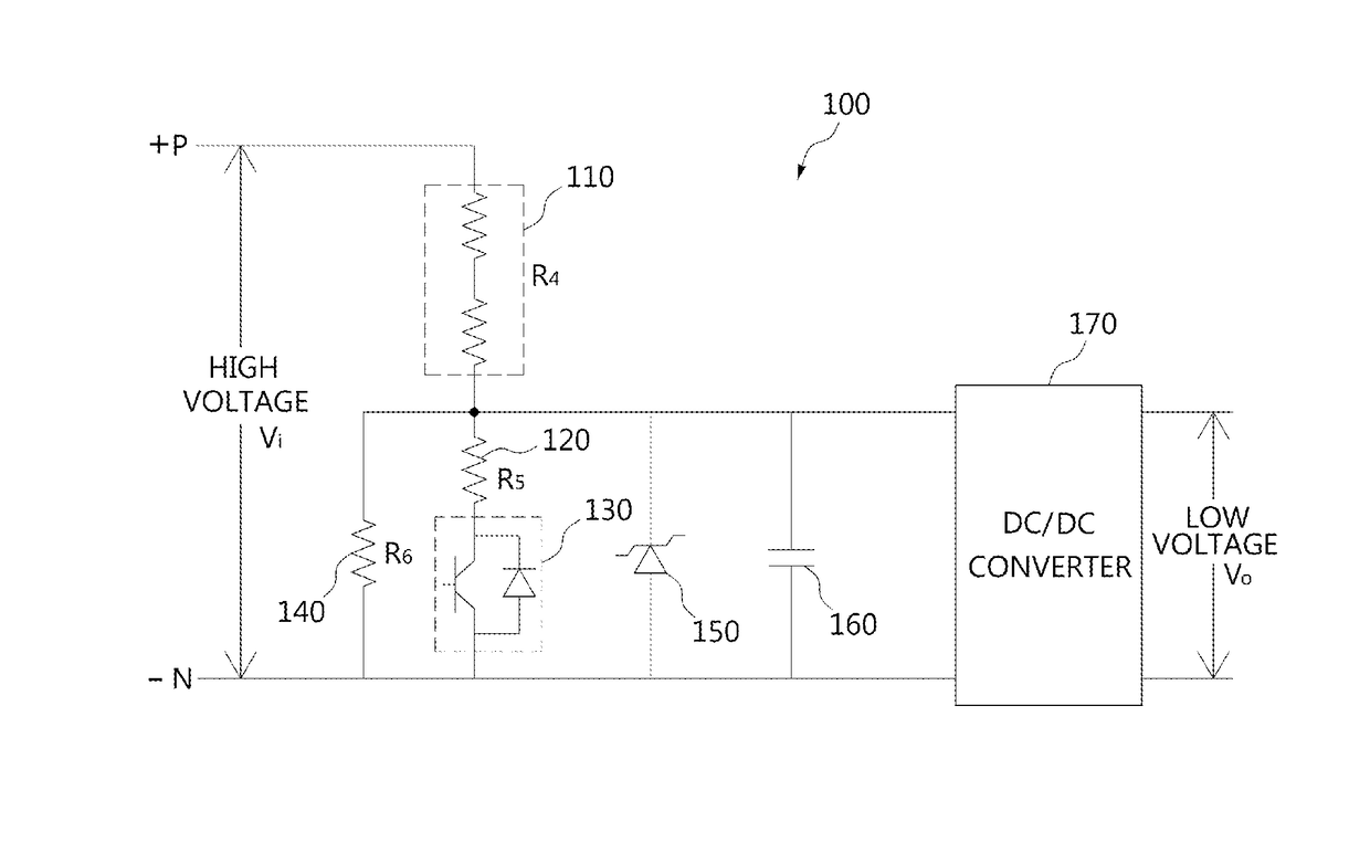
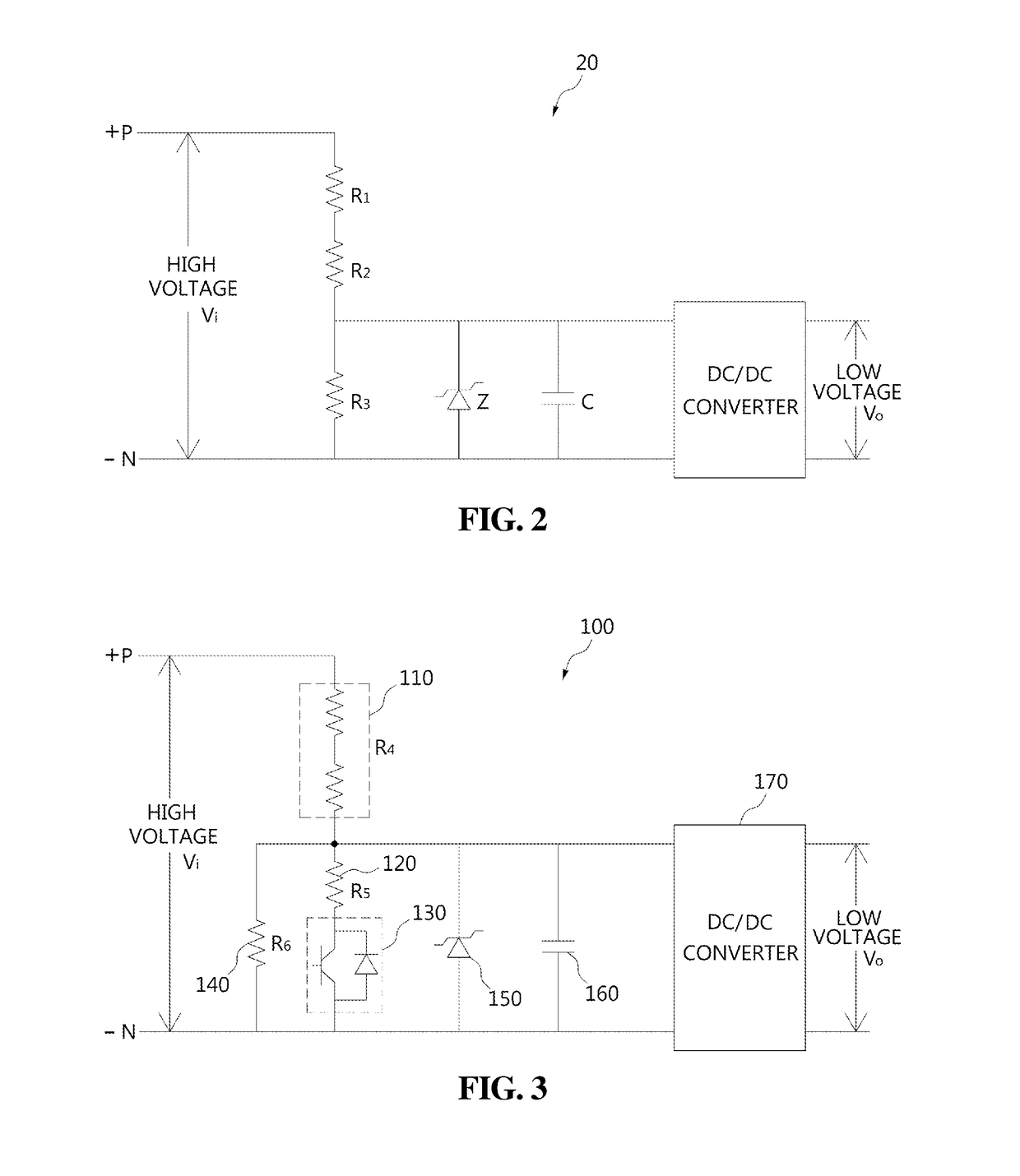
[0040]The power control apparatus 100 according to the first embodiment of the present invention includes at least one first resistor R4 110, connected between the P and N buses of the MMC, and a second resistor R5 120, connected in series with the first resistor R4 110. The first resistor 110 is implemented such that one or more resistors are connected in series. A switch 130 is connected in series with the second resistor 120. The switch 130 may be implemented in various manners using a mechanical switch, a relay contact switch, or a semiconductor switch element. For example, an Insulated-Gate Bipolar Transistor (IGBT) or a Field Effect Transistor (FET) may be used as the semiconductor switch element. When a mechanical switch or a relay contact switch is used, a backward diode for limiting the flow of current is preferably connected in series therewith. The ON / OFF switching operation of the switch 130 is controlled by a control unit (not shown). Since the switch 130 is connected i...

Example

[0054]Further, in the power control apparatus 200 according to the second embodiment of the present invention, a switch 250 is connected between the junction of the first resistor 210 and the second resistor 220 and the junction of the third resistor 230 and the Zener diode 240. This switch 250 may be implemented using a mechanical switch, a relay contact switch, or the like. When a relay contact switch is applied, it is connected in series with a diode so that the diode blocks the flow of reverse current. Although not shown in the drawing, the operation of the switch 250 is controlled by a control unit (not shown). That is, the control unit adjusts the magnitude of the current to be supplied to the Zener diode 240 by controlling the switching operation of the switch 250, thus reducing the burden on the Zener diode 240. In the present embodiment, the switch is implemented as, for example, a B contact switch, in which the initial state thereof is maintained in a shorted state. In thi...


PUM


Abstract

Disclosed herein is a power control apparatus for sub-modules in an MMC, which controls stable supply of power to sub-modules in MMC connected to an HVDC system and a STATCOM. The power control apparatus includes at least one first resistor connected between P and N buses of MMC; a second resistor connected in series with the first resistor; a switch connected in series with the second resistor; a third resistor connected in parallel with the second resistor and the switch which are connected in series; a Zener diode connected in parallel with the third resistor; and a DC/DC converter connected between both ends of the Zener diode and configured to convert voltage across both ends of the Zener diode into low voltage, and supply the low voltage to the sub-modules, wherein a magnitude of current flowing through the Zener diode is controlled depending on ON/OFF switching of the switch.

Description

TECHNICAL FIELD[0001]The present invention generally relates to a power control apparatus and, more particularly, to a power control apparatus for sub-modules in a Modular Multilevel Converter (MMC), which controls the stable supply of power to sub-modules in an MMC connected to a High Voltage Direct Current (HVDC) system and to a Static Synchronous Compensator (STATCOM).BACKGROUND ART[0002]Generally, in High Voltage Direct Current (HVDC) systems, Alternating Current (AC) power produced in a power plant is converted into DC power and the DC power is transmitted, and a power receiving stage re-converts the DC power into AC power and supplies the AC power to a load. Such an HVDC system is advantageous in that power may be efficiently and economically transmitted via voltage boosting, and in that connections between heterogeneous systems and long-distance high-efficiency power transmission are possible. Further, a Static Synchronous Compensator (STATCOM) is a kind of Flexible AC Transm...

Claims


Application Information

Patent Timeline
IPC IPC(8): H02M1/08H02M3/04H02M7/217H02M1/00
CPCH02M1/08H02M7/217H02M3/04H02M2001/0009H02M2001/0048H02M7/19H02M7/49H02M1/0006H02M7/4835Y02B70/10H02M1/0009H02M1/0048
Inventor KIM, JUNE-SUNGJUNG, HONG-JUPARK, JUNG-SOOLEE, DOO-YOUNGCHOI, JONG-YUN
Owner HYOSUNG HEAVY IND CORP
Why Eureka
Try Eureka