
Apparatus and method for testing electronic equipment

Inactive Publication Date: 2013-02-21
TELEPLAN INT
View PDF2 Cites 0 Cited by
  • Summary
  • Abstract
  • Description
  • Claims
  • Application Information

AI Technical Summary

Benefits of technology

The invention helps to create higher temperatures in a powered electronic device by blocking its ventilation holes and insulating its internal components from external factors. This can lead to more efficient testing for any faults that might occur.

Problems solved by technology

First, the thermal treatment, made of fabric and / or other materials, blocks the ventilation holes in the walls of the device, defeating their intended purpose and preventing the heat generated by the powered internal electrical components from escaping the box by free flow of air.
Secondly, the insulating effect of the treatment influences the rate of increase of the temperatures inside the device, as well as the ultimate level of steady state temperature reached.

Method used


Image

  • Apparatus and method for testing electronic equipment
  • Apparatus and method for testing electronic equipment
  • Apparatus and method for testing electronic equipment

Examples


Embodiment Construction

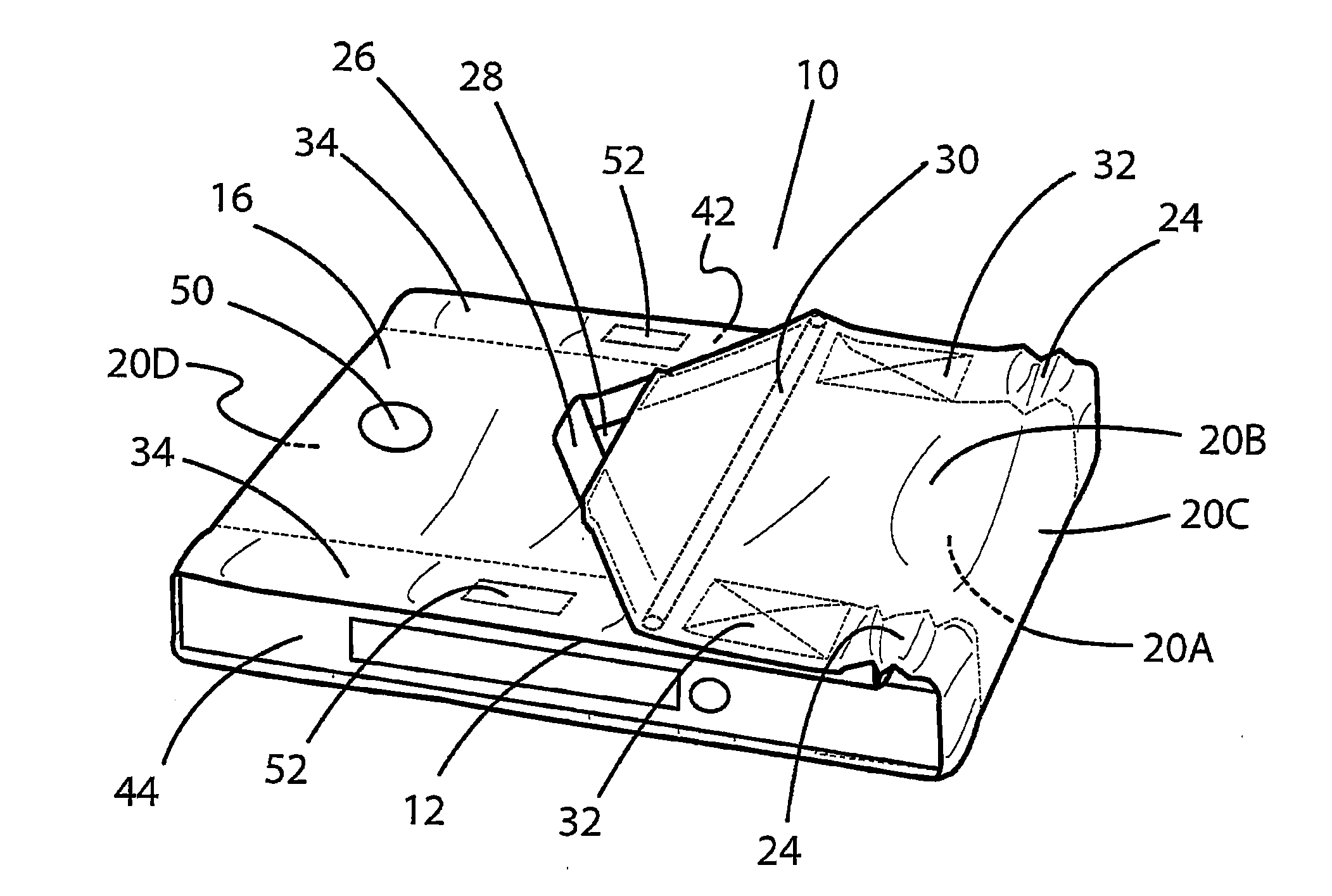
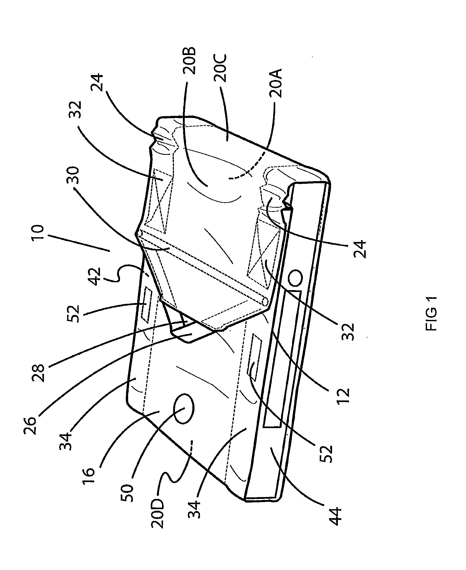
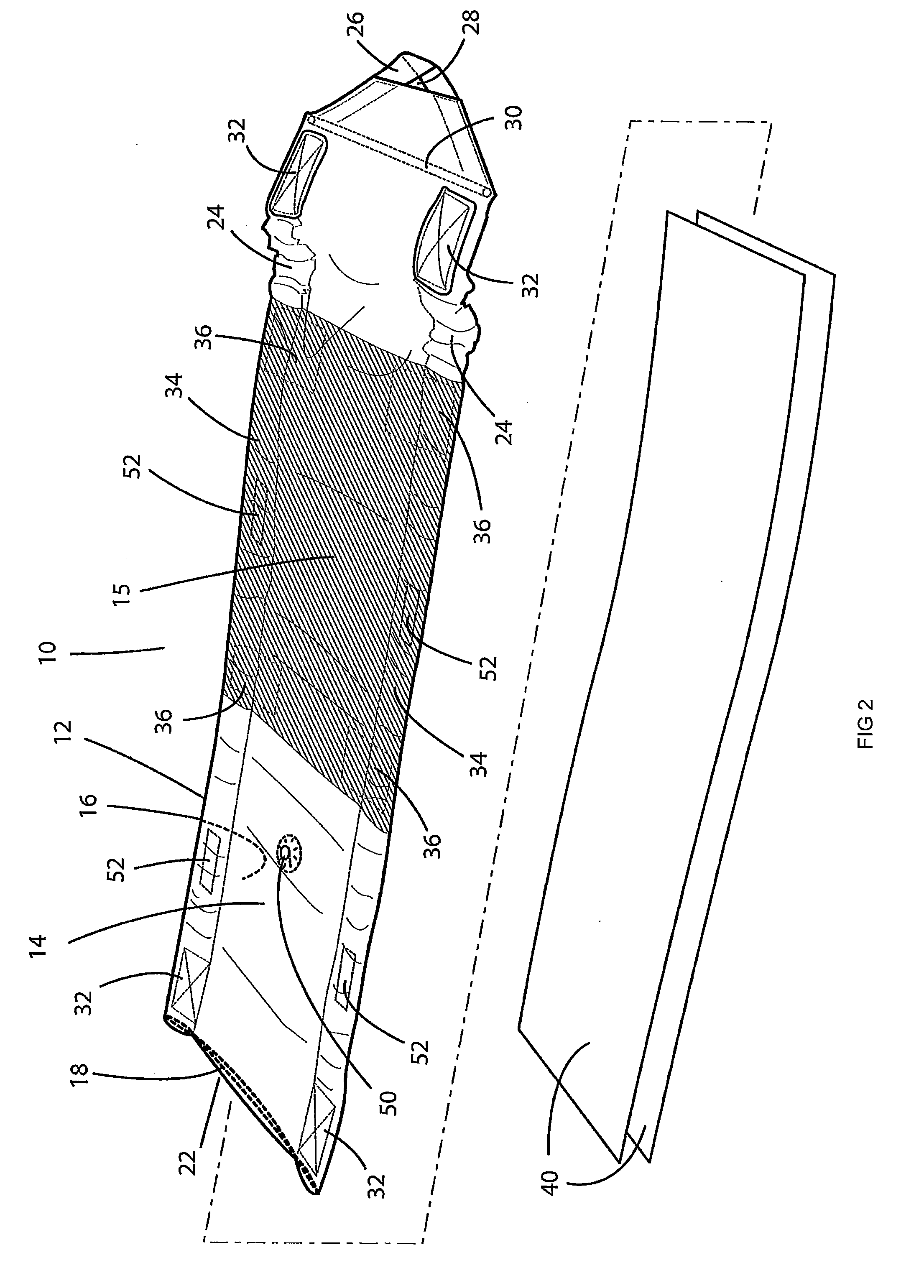
[0014]Referring to the drawings in which like reference numbers refer to like elements, thermal test wrap 10 is comprised of a web 12 having an inside 14 and an outside 16 surface. In the depicted embodiment, the web 12 has a thermally insulating element 18, which may include insulating material held between a fabric or film comprising the inside and outside surfaces, or may also or alternatively include a reflective material.

[0015]Web 12 has sections. In the depicted embodiment, there are four sections 20A, 20B, 20C and 20D corresponding to four of the six sides that set top boxes are typically configured to have. This embodiment covers four of six walls, while intentionally leaving the front and back of the box open as is necessary for test access to buttons and the infrared receiver input on the front panel, and the attachment of power and signal input and output cables on the backside.

[0016]All or part of the inside surface 14 may have a different color than the rest to facilita...


PUM


Abstract

A thermal wrap for testing electronic components has a web having an inside and an outside surface and a first end and a second end and a thermal element incorporated in said web. An edge element incorporated substantially along at least one edge of said web promotes a thermal seal between said web and the electronic component being tested when the electronic component in installed in the wrap. A closure disposed on the ends may be reversibly closed sufficiently tightly to promote the thermal seal.

Description

BACKGROUND OF THE INVENTION[0001]1. Field of the Invention[0002]The field of the invention is in testing electronic equipment.[0003]2. Related Art[0004]Elevated temperature is a known accelerator in the failure of electronic products and components. Heat is a common problem in the field application of Set Top boxes (“STBs”) wherein the end user often encloses the device in an entertainment center having little or no ventilation or air movement. Certain types of faults occur at elevated temperature but not at room temperature. Certain types of faults occurring at elevated temperature are precursors to eventual failure at lower temperatures. In the after-market repair industry the goal is to find and repair the root cause of all possible forms of malfunction in faulty products returned by customers. Testing at elevated temperature is a means of improving the overall rate of fault detection over testing exclusively at room temperature. The same is true for testing the quality of newly ...

Claims


Application Information

Patent Timeline
IPC IPC(8): G01R1/00
CPCG01R31/003
Inventor ALBERT, GLENN D.
Owner TELEPLAN INT
Learn More