Surface-emitting laser and method of fabrication thereof
Inactive Publication Date: 2003-07-15
SEIKO EPSON CORP
View PDF14 Cites 6 Cited by
Summary
Abstract
Description
Claims
Application Information
AI Technical Summary
This helps you quickly interpret patents by identifying the three key elements:
Problems solved by technology
Method used
Benefits of technology
This makes it possible to form an insulating film below the region where part of the multi-layer film will form the embedding layer. Since the electrical resistance of the multi-layer film is low
Problems solved by technology
It is therefore impossible to cut out the higher transverse modes.
This makes it impossible for a conventional surface-emittin
Method used
Image
Click on the blue label to locate the original text in one second.
Reading with bidirectional positioning of images and text.
Examples
first embodiment
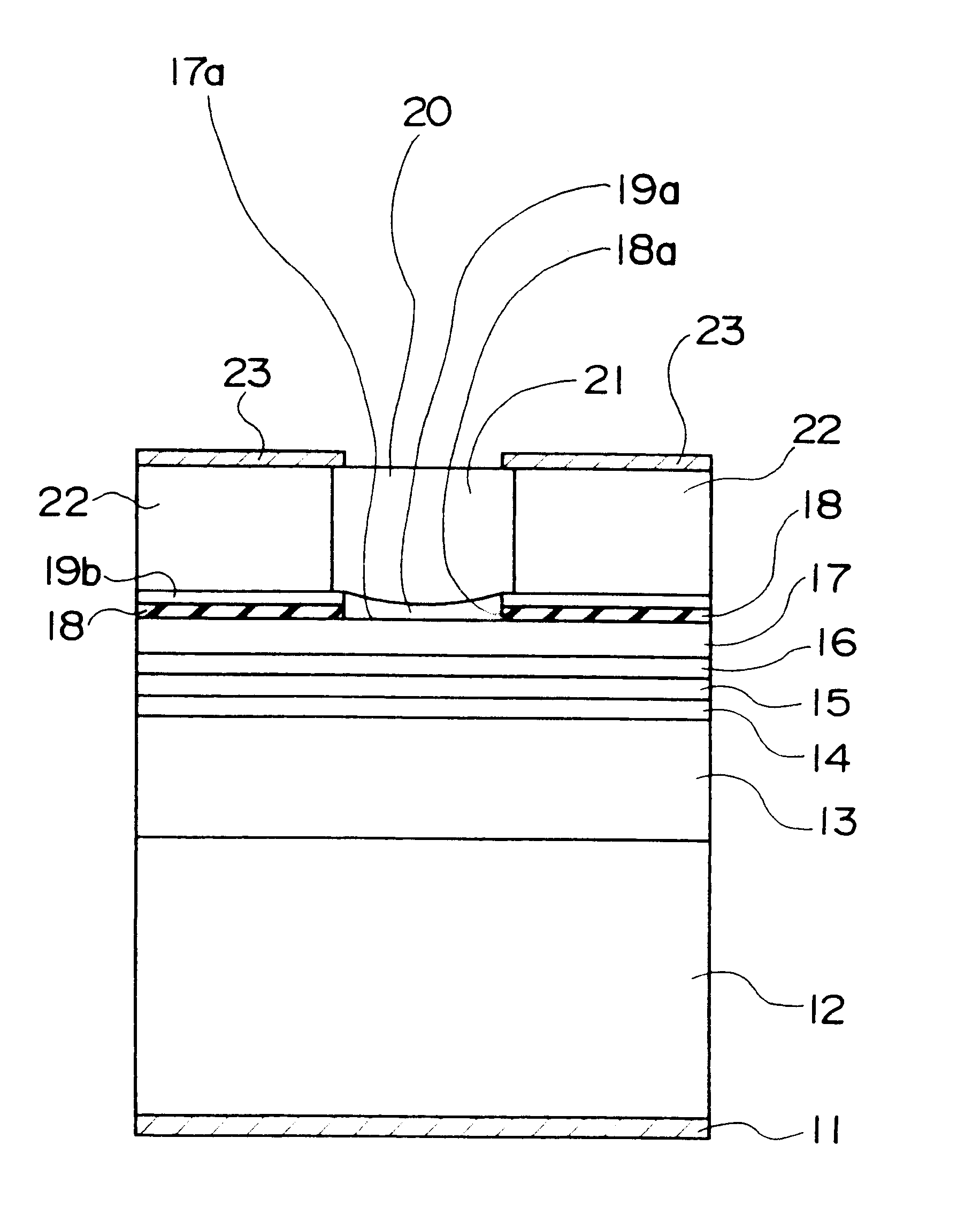
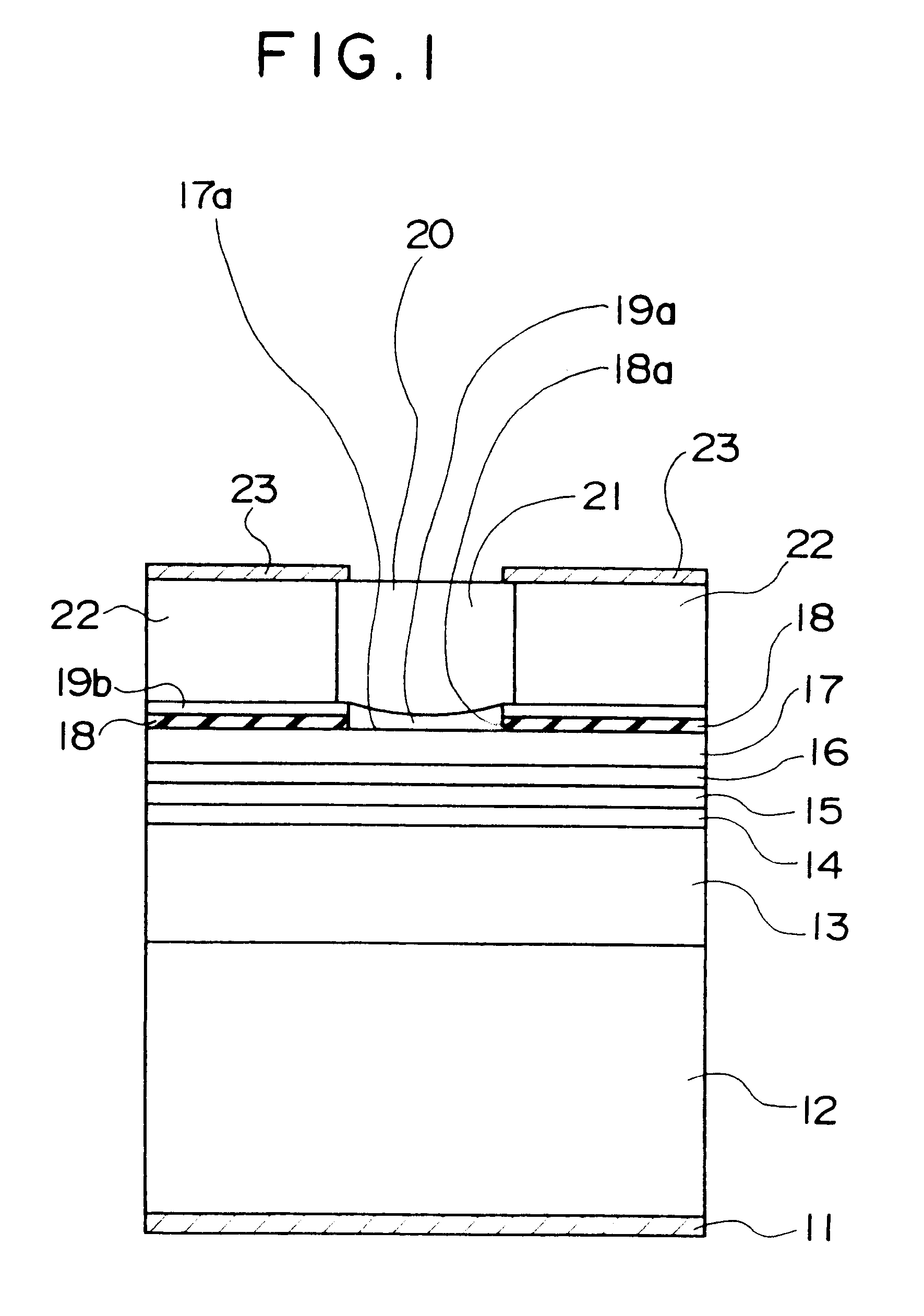
A cross-sectional view of a surface-emitting laser in accordance with the present embodiment is shown in FIG. 1.
In this figure, a lower electrode 11 is formed on a rear surface of a semiconductor substrate 12 formed of n-type GaAs or the like, by way of example.
A lower reflective mirror 13 is formed above the semiconductor substrate 12. The lower reflective mirror 13 is a distributed reflection type of multi-layer reflective mirror (a distributed Bragg reflector, abbreviated to DBR) having a reflectivity of at least 99.5% with respect to light of wavelengths in the vicinity of 800 nm, formed of 40 pairs of n-type Al.sub.0.8 Ga.sub.0.2 As layers and Al.sub.0.15 Ga0.85.As layers, by way of example.
A cladding layer 14, an active layer 15, and another cladding layer 16 are formed in that order from the bottom upward on the lower reflective mirror 13. The cladding layer 14 is formed of an n-type Al.sub.0.7 Ga.sub.0.3 As layer, by way of example, the active layer 15 is a multi-well struct...
second embodiment
A cross-sectional view of a surface-emitting laser in accordance with a second embodiment is shown in FIG. 4.
In this figure, a lower electrode 11 is formed on a rear surface of a semiconductor substrate 112 formed of n-type GaAs or the like, by way of example.
A lower reflective mirror 113 is formed above the semiconductor substrate 112. The lower reflective mirror 113 is a distributed reflection type of multi-layer reflective mirror (a distributed Bragg reflector, abbreviated to DBR) having a reflectivity of at least 99.5% with respect to light of wavelengths in the vicinity of 980 nm, formed of 40 pairs of GaAs layers and Al.sub.0.8 Ga.sub.0.2 As layers, by way of example.
A cladding layer 114, an active layer 115, and another cladding layer 116 are formed in that order from the bottom upward on the lower reflective mirror 113. The cladding layers 114 and 116 are formed of Al.sub.0.3 Ga.sub.0.7 As, by way of example, and the active layer 115 is a multi-well structure formed of InGaA...
PUM
Abstract
The present invention provides a surface-emitting laser which is capable of emitting a laser beam with a single-peak spatial distribution, but is incapable of guiding modes other than a single transverse mode, and a method of fabrication thereof. The laser comprises a columnar portion (20) that forms part of a reflective mirror on a light-emitting side and an embedding layer (22) that surrounds the periphery of this columnar portion (20). The columnar portion (20) is made of single-crystalline AlGaAs and the embedding layer (22) is made of polycrystalline AlGaAs. The absolute refractive index of the embedding layer (22) is slightly smaller than that of the columnar portion (20), thus a laser beam with a single transverse mode is obtained.
Description
The present invention related to a single transverse mode type of surface-emitting laser and a method of fabrication thereof.BACKGROUND OF ARTA surface-emitting laser is known in the art in which a resonator post is formed as a column from an upper mirror and an embedding layer is formed around the periphery thereof. The resistance of this embedding layer is increased by ion implantation to ensure that current flows only through the resonator post.However, the surface-emitting laser of this configuration emits laser beams in transverse modes that are controlled by the distribution of current, because there is substantially no difference in absolute refractive index (refractive index with respect to vacuum) between the resonator post and the embedding layer. In other words, a large proportion of the current flows through outer peripheral portions of the resonator post so that higher, ring-shaped transverse modes appear.Furthermore, the other structure of the surface emitting laser ha...
Claims
Application Information
Patent Timeline
Application Date:The date an application was filed.
Publication Date:The date a patent or application was officially published.
First Publication Date:The earliest publication date of a patent with the same application number.
Issue Date:Publication date of the patent grant document.
PCT Entry Date:The Entry date of PCT National Phase.
Estimated Expiry Date:The statutory expiry date of a patent right according to the Patent Law, and it is the longest term of protection that the patent right can achieve without the termination of the patent right due to other reasons(Term extension factor has been taken into account ).
Invalid Date:Actual expiry date is based on effective date or publication date of legal transaction data of invalid patent.