Electric compressor

Inactive Publication Date: 2016-02-11
TOYOTA IND CORP
View PDF5 Cites 2 Cited by
  • Summary
  • Abstract
  • Description
  • Claims
  • Application Information

AI Technical Summary

Benefits of technology

[0006]In an electric compressor according to an aspect of the present invention, the first vibration damper is disposed between the housing and the supporting member so as to keep the housing free from contact with the supporting member and, therefore, the first vibration damper prevents transmission of vibration of the housing to the target through the supporting member. The housing and the target are not in contact with each other, so that direct transmission of the vibration from the housing to the target is prevented. The first vibration damper is formed hollow. Spe

Problems solved by technology

Heat is generated relatively easily in such solid rubber due to vibration and, therefore, the durab

Method used


Image

  • Electric compressor
  • Electric compressor
  • Electric compressor

Examples


first embodiment

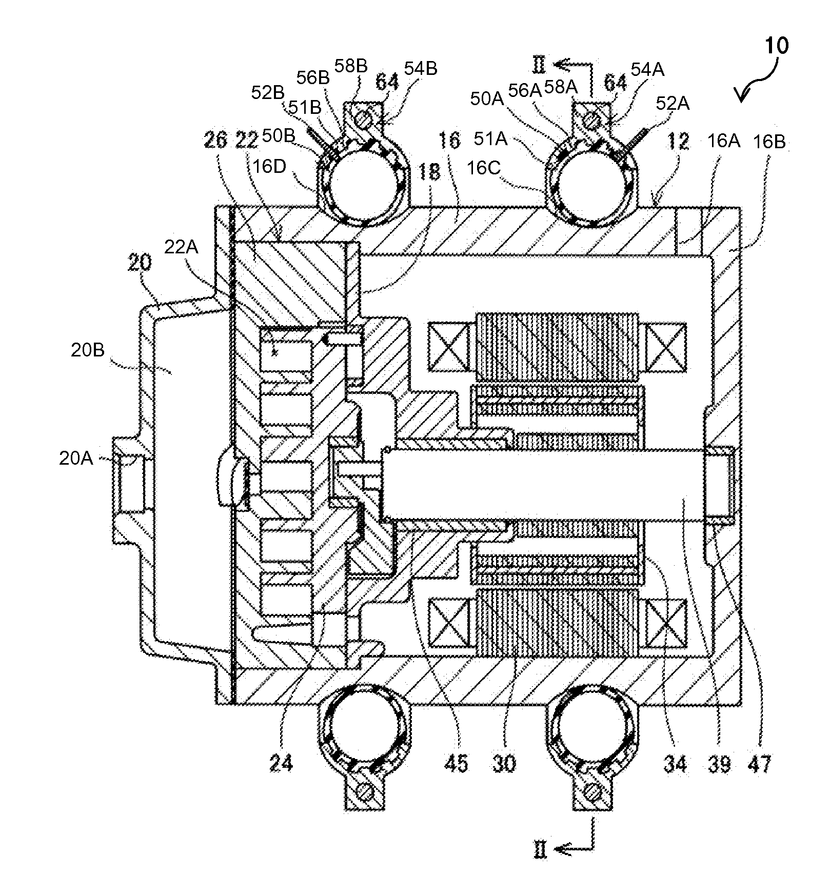
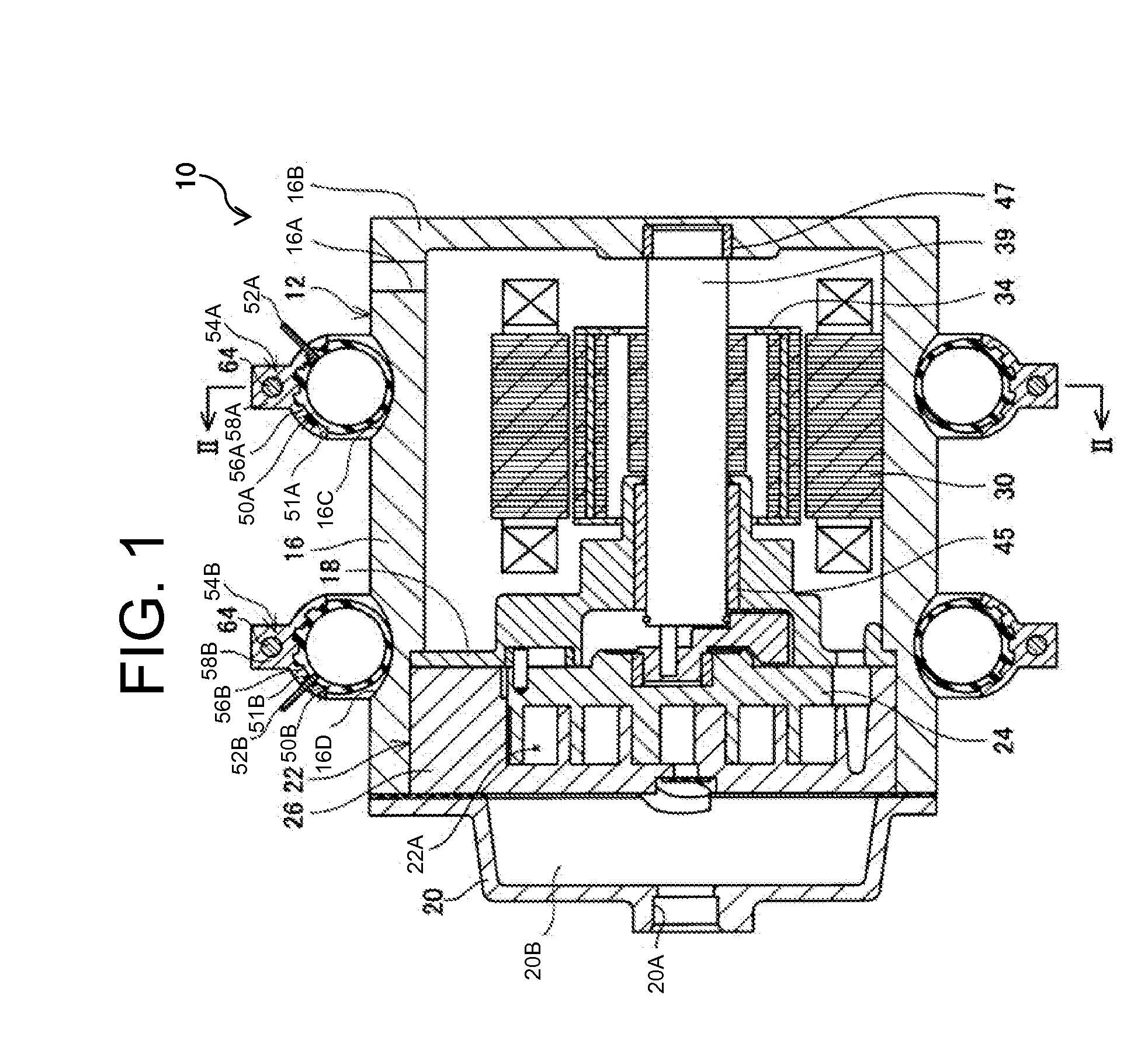
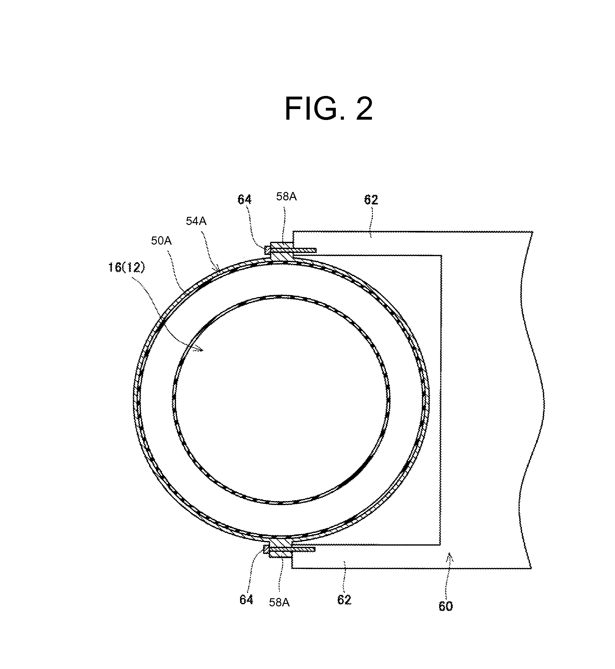
[0025]A first embodiment of the present invention will now be described with reference to FIGS. 1 to 4. An electric compressor, which is designated by numeral 10, is mounted to an electric vehicle or a hybrid car and adapted for use in a vehicle air conditioner. In FIG. 2, an engine to which the electric compressor 10 is mounted is designated by numeral 60, but in FIGS. 1, 3, and 4 the engine 60 is not illustrated. It is to be noted in the drawings some cross sections are not indicated by hatching and also that in FIG. 2 the internal configuration of a housing 12 is not illustrated. Referring to FIG. 1, the electric compressor 10 includes the housing 12 of a substantially cylindrical shape, a rotating shaft 39 that is rotatably supported in the housing 12, a motor including a stator coil 30 and a rotor 34 and a compression part 22. The motor (30, 34) and the compression part 22 are housed in the housing 12. The electric compressor further includes a pair of tubes 50A, 50B that exten...

first modification

[0044]A first modification of the present invention will now be described with reference to FIG. 5. In the following description of the first modification, only the differences form the first embodiment will be described and the detailed description on the configurations that are common to the first embodiment will be omitted. This also applies to other embodiments and modifications unless otherwise specified. It is to be noted that the internal configuration of the housing 12 is not illustrated in FIG. 5. This also applies to FIGS. 6 and 7, and FIGS. 9 to 14. In the first modification, substantially the same tube assemblies each including a tube and a rim are fitted in the respective grooves 16C, 16D of the motor housing 16. This also applies to other embodiments and modifications which will be described hereinafter.

[0045]The first modification of FIG. 5 is different from the first embodiment in the configuration of the tube. Specifically, the first modification differs from the fi...

second modification

[0047]A second modification of the present invention will now be described with reference to FIGS. 6 to 8. The second modification is different from the first modification in that two sheets 70 are added, i.e. one sheet 70 disposed between the rim 254A and the tube 150A and the other sheet 70 between the rim 254A and the tube 152A. FIG. 6 shows a state in which the air pressure of the tubes 150A, 152A is maintained within the specified range, and FIG. 7 shows a state in which some air is released from the tube 152A, so that the air pressure of the tube 152A falls below the specified range. FIG. 8A is a cross-sectional view of the tube 152A of FIG. 6, and FIG. 8B is a cross-sectional view of the tube 152A of FIG. 7. The cross sections in FIGS. 8A and 8B are taken along a plane that is perpendicular to the extending direction of the tube 152A. As shown in FIG. 6 and FIG. 8A, the sheet 70 that is disposed between the rim 254A and the tube 152A is in contact with both of the rim 254A an...


PUM


Abstract

An electric compressor includes a compression part, a motor that drives the compression part, a cylindrical housing that accommodates therein the compression part and the motor, a supporting member, and a first vibration damper. The supporting member supports the housing and is configured to be fixed to a target to which the compressor is attached. The first vibration damper is disposed between the housing and the supporting member so as to keep the housing free from contact with the supporting member and the target. The first vibration damper has therein a hollow enclosed space.

Description

BACKGROUND OF THE INVENTION[0001]The present invention relates to an electric compressor.[0002]Japanese Unexamined Patent Application Publication No. 2013-224652 discloses a cylindrical electric compressor adapted for use in a vehicle air conditioner. The electric compressor includes a housing, two supporting members, and a vibration damper. The housing has therein a motor and a compression part that is driven by the motor. The supporting members are formed in a semi-cylindrical shape and support the housing by holding the housing on the periphery thereof. The supporting members are fixed to any part or target in the engine compartment of the vehicle (e.g. a vehicle frame or the engine). In other words, the housing is fixed to the target via the supporting members. The vibration damper is disposed between each of the supporting members and the housing so that the supporting members and the housing are not in direct contact with each other.[0003]According to the configuration of the ...

Claims


Application Information

Patent Timeline
IPC IPC(8): F04C29/06F04C18/02F04C29/00
CPCF04C29/06F04C29/0085F04C18/0207F01C21/007F04C2270/12
Inventor FUKASAKU, HIROSHI
Owner TOYOTA IND CORP
Why Eureka
Try Eureka