
Communication apparatus

a technology of communication apparatus and data transmission, applied in the direction of digital output to print units, instruments, computing, etc., can solve the problems of unnecessary data communication, take a relatively long time to complete,

Active Publication Date: 2006-08-03
BROTHER KOGYO KK
View PDF9 Cites 58 Cited by
  • Summary
  • Abstract
  • Description
  • Claims
  • Application Information

AI Technical Summary

Benefits of technology

The invention prevents the output data from being transmitted unnecessary.

Problems solved by technology

If the data transmission is stopped as an abnormal condition occurs and the image represented by the image data cannot be printed on the data reception side, it may take a relatively long time until the abnormal condition is cancelled.
If, during such a period, the transmission apparatus repeatedly attempts to transmit the image data, unnecessary data communication is executed.

Method used


Image

  • Communication apparatus
  • Communication apparatus
  • Communication apparatus

Examples


embodiment

[0045] Hereinafter, referring to the accompanying drawings, a communication system according to an illustrative embodiment of the invention will be described.

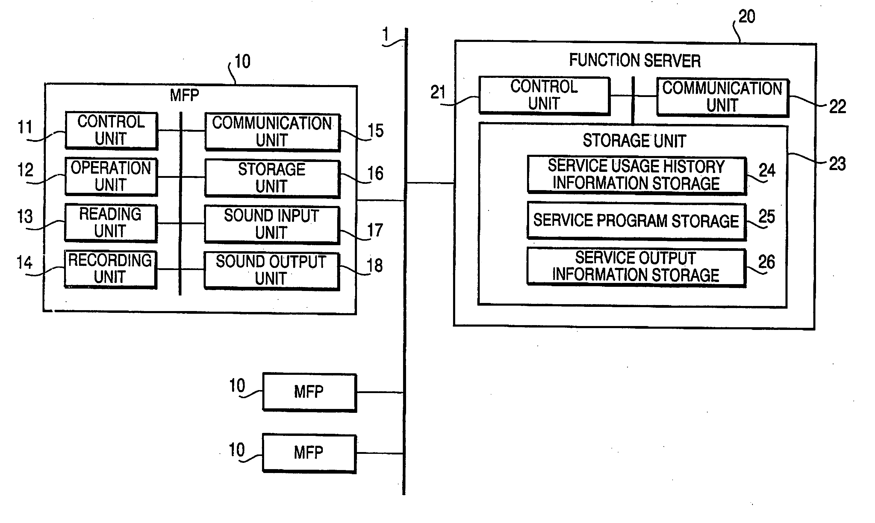
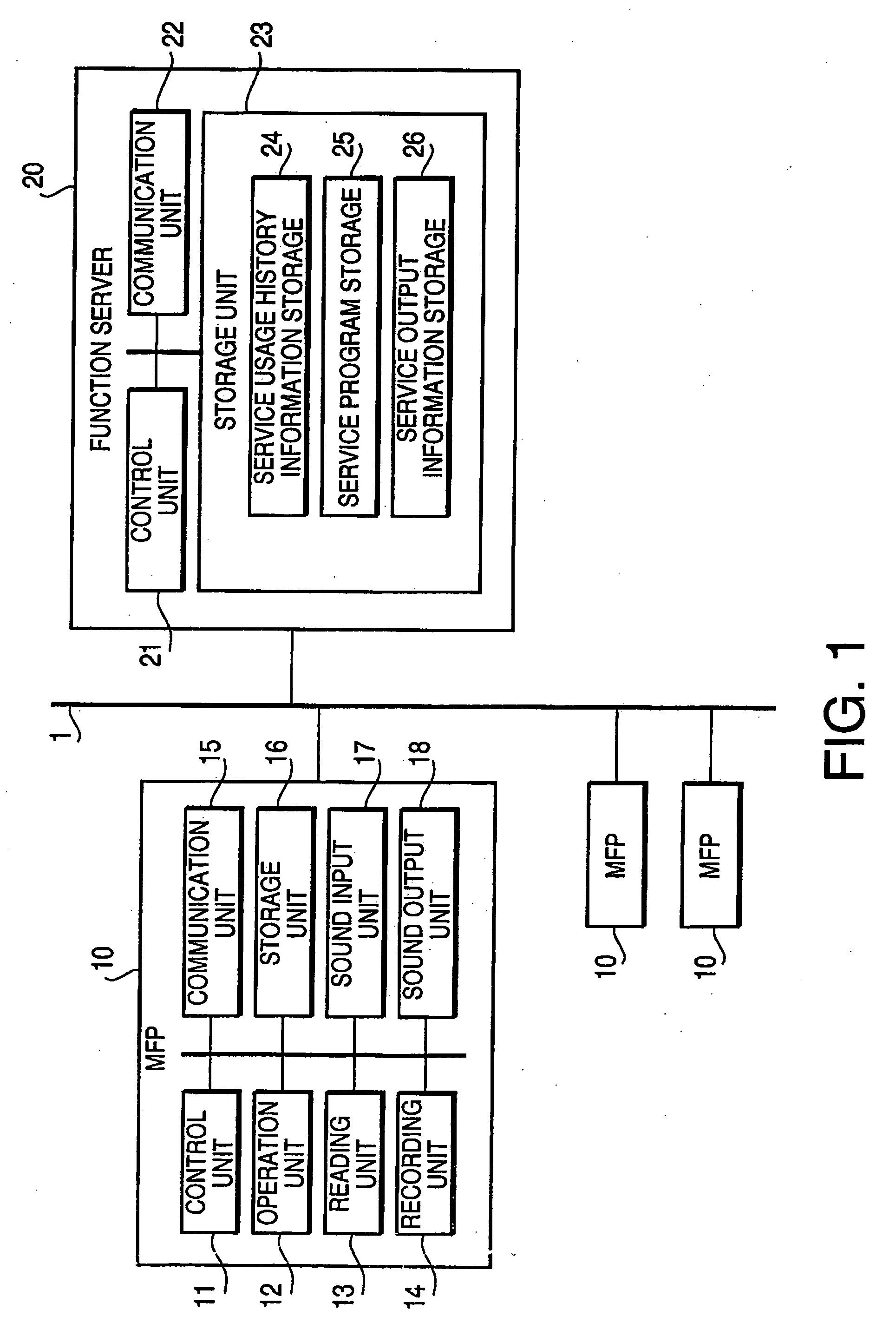
[0046]FIG. 1 is a block diagram illustrating a system configuration of the communication system according to an illustrative embodiment. The communication system is provided with multiple MFPs 10, 10, . . . and a function server 20, which are connected with each other through a network 1 (which is the Internet, in the illustrative embodiment) so that data communication is performed thereamong.

[0047] The MFP 10 is configured to have functions of a telephone (audio communication), a scanner, a printer, a copier, and a facsimile machine. As show in FIG. 1, the MFP 10 includes a control unit 11, an operation unit 12, a reading unit 13, a recording unit 14, a communication unit 15, a storage unit 16, a sound input unit 17 and a sound output unit 18.

[0048] The control unit 11 includes a well-known microcomputer provided with a CPU...


PUM


Abstract

A communication system including a transmission apparatus configured to transmit output data and a reception apparatus configured to receive the output data. The reception apparatus includes an output unit configured to execute an outputting procedure based on the output data, an abnormal state notification unit configured to transmit abnormal state notification data to the transmission apparatus, and a retransmission requesting unit configured to transmit retransmission request data if the outputting procedures is not executed normally. Further, the transmission apparatus is provided with an output data transmitting unit configured to transmit the output data to the reception apparatus, a transmission terminating unit configured to terminate transmission of the output data if the abnormal state notification data is received from the reception apparatus, and an output data retransmitting unit configure to transmit the output data requested by the retransmission requesting unit to the reception apparatus when the retransmission request data is received.

Description

Cross-Reference to Related Application [0001] This application is related to Japanese Patent Application No. 2005-023951, filed on Jan. 31, 2005. The entire subject matter of the application is incorporated herein by reference. BACKGROUND [0002] 1. Technical Field [0003] Aspects of the invention relates to a data transmission apparatus configured to transmit output data, a data reception apparatus configured to receive the output data transmitted from the data transmission apparatus, and a communication system including the data transmission apparatus and the data reception apparatus. [0004] 2. Description of Related Art [0005] The communication system of the above-described type has been known. An example of such a system is a facsimile system. In the facsimile system, the data transmission apparatus (i.e., a facsimile machine of a transmitting station) transmits image data (i.e., output data) representing an image of an original scanned by the facsimile apparatus at the transmitti...

Claims


Application Information

Patent Timeline
Patent Type & Authority Applications(United States)
IPC IPC(8): H04M3/00
CPCH04N1/32122H04N1/32619H04N2201/0094H04N2201/3202H04N2201/3205H04N2201/3214H04N2201/3215H04N2201/3216H04N2201/3219H04N2201/3221H04N2201/3223H04N2201/3226H04N2201/3274
Inventor MATSUDA, MAKOTO
Owner BROTHER KOGYO KK
Learn More