Double mobility prothese

a technology of mobility protheses and joint replacements, applied in the field of joint replacements, can solve problems such as difficult or even impossible, and achieve the effect of preventing dislocation

Active Publication Date: 2018-01-11
WALDEMAR LINK GMBH & CO
View PDF3 Cites 1 Cited by
  • Summary
  • Abstract
  • Description
  • Claims
  • Application Information

AI Technical Summary

Benefits of technology

[0012]It is therefore an object of the present invention to provide an insert and a joint system which also prevent dislocation in patients whose constitution is impaired. Another object is to enable simple, intraoperative assembly without compromising the functionality of the joint endoprosthesis, while keeping the strain on the joint components to a minimum.

Problems solved by technology

Thus, even those patients may now receive a joint replacement for whom this was previously difficult or even impossible on account of their tissue condition.

Method used


Image

  • Double mobility prothese
  • Double mobility prothese
  • Double mobility prothese

Examples


Embodiment Construction

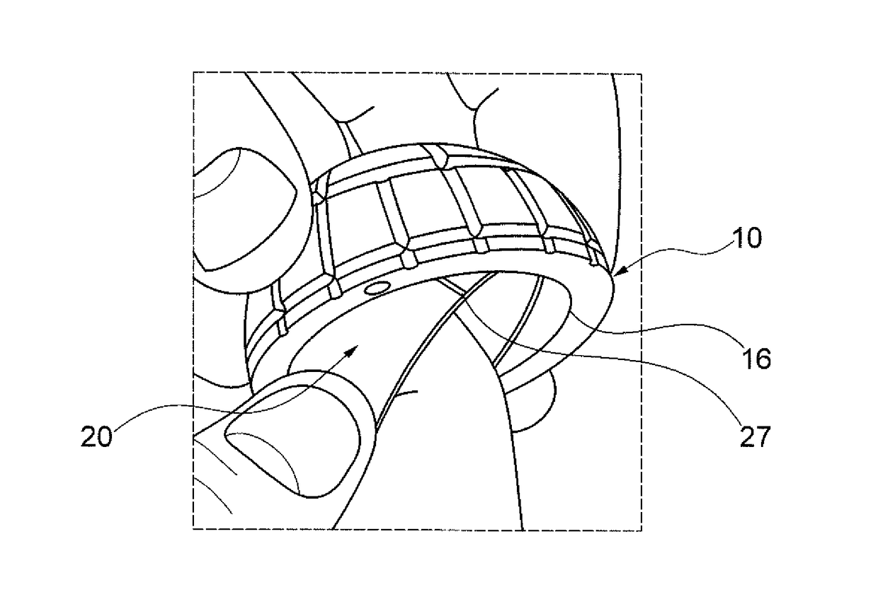
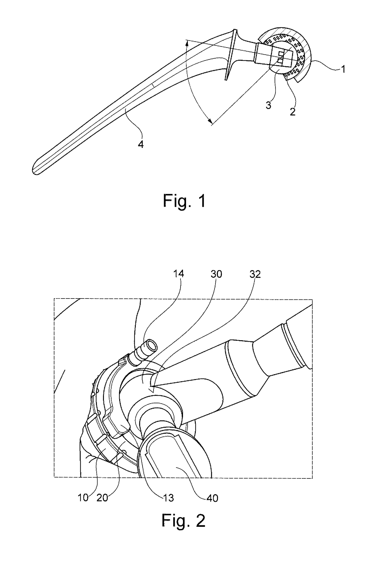
[0050]FIG. 1 shows the assembled state of a double-joint hip endoprosthesis which is also termed double mobility prosthesis. As already described above, prior art prostheses of this kind, despite having a small femoral head 3, provide the degree of movement of a large-head prosthesis. The implant, shown in the abduction position in FIG. 1, combines the advantages of less abrasion due to a smaller femoral head with the greater degree of movement provided by a large-head prosthesis as it is composed of two partial joints.

[0051]The first partial joint is situated between the hip socket 1 implanted in the pelvic bone and a joint insert 2. The second partial joint is formed between the joint insert 2 and the femoral head 3. As can be recognized in FIG. 1 from the deflection of the implant at a maximum abduction angle, the degree of movement is increased in that the prosthesis stem 4, situated below the femoral head 3, abuts against the rim of the joint insert 2 which, however, is deflect...


PUM


Abstract

Provided is a joint replacement with a joint socket (10) having a concave joint surface (11), and with a joint insert (20) having a concave joint surface (21) and a convex joint surface (22) which are each delimited by a peripheral edge (23, 24). The convex joint surface (22) of the joint insert (20) is designed, in the assembled state, to form a first partial joint with the concave joint surface (11) of the joint socket (10). Moreover, the concave joint surface (21) of the joint insert (20) is designed, in the assembled state, to form a second partial joint with the convex joint surface (32) of a joint head (30). The joint socket (10) and the joint insert (20) each have a securing means (12, 25, 26) for preventing dislocation of the joint replacement.

Description

FIELD OF THE INVENTION[0001]The present invention relates to a joint replacement with two partial joints as well as to an insertion aid for said joint replacement.PRIOR ART[0002]Replacing an injured or worn-out natural joint with an artificial joint is a common procedure. Now, in the meantime, there are artificial joint replacements for a multiplicity of natural joints, such as, for example, for the hip joint, the shoulder joint, the elbow joint, the ankle joint, the finger joint or the knee joint. Total joint replacements are composed of at least two components that are fixed to the opposite bones. Total hip endoprostheses of this kind thus comprise a joint socket to be implanted in the acetabulum of a patient, as well as a joint head on a prosthesis stem to be anchored in the femur.[0003]Generally, artificial joints are not just copies of natural joints in terms of their dimensions and structure. As regards, for instance, artificial hip joints, the joint heads are frequently given...

Claims


Application Information

Patent Timeline
Patent Type & Authority Applications(United States)
IPC IPC(8): A61F2/34A61F2/30A61F2/32A61F2/36A61F2/46
CPCA61F2/34A61F2/4637A61F2002/30367A61F2002/3409A61F2002/3411A61F2002/3208A61F2002/3233A61F2002/3241A61F2/3609A61F2002/345A61F2002/3438A61F2002/3617A61F2/32A61F2002/305A61F2002/30426A61F2002/30652A61F2002/30593
Inventor LINK, HELMUTJENDRO, GUNTHERGRADL, GEORG
Owner WALDEMAR LINK GMBH & CO
Why Eureka
Try Eureka