Lifting hook bias angle monitoring apparatus, vertical hoisting monitoring apparatus and mobile crane

a monitoring apparatus and bias angle technology, applied in the field of cranes, can solve problems such as detection deviation, and achieve the effect of smooth change of the hoisting sta

Inactive Publication Date: 2018-01-11
LIN HANDING
View PDF5 Cites 9 Cited by
  • Summary
  • Abstract
  • Description
  • Claims
  • Application Information

AI Technical Summary

Benefits of technology

[0041]Beneficial effects of the hook bias angle monitoring and vertical hoisting monitoring apparatus: 1. translating the hook bias angle detection into the detection of dip angle between the platform plane and the horizontal plane (surface-to-plane), overcoming the influence of pulley block lifting force point skewing and resultant lifting load force point skewing on the hook bias angle detection, only in this way can the correct detection of the hook angle be achieved. 2. The operator can correctly control the hook operation in response to the real-time hook bias angle orientation change image displayed in the operating chamber, smoothly change the hoisting state and correct the orientation of hook bias angle during hoisting upon the rotation of fixed and movable pulley axes around the pulley block lifting force line. 3. The real-time hook bias angle is displayed in both operating of the co-hoisting crane, making vertical hoisting available; 4. The hook bias angle detection apparatus has overcome the bias of sling-based hook bias angle detection technique, which is applicable to both single-crane hoisting and lifting mobile crane with the function of vertical lifting monitoring, and is in demand for long term.

Problems solved by technology

The offset of the resultant lifting load force point of lifting hook also possibly leads to a deviation of the detection result of the bias angle of the lifting hook using the angle measuring instrument established on the platform surface perpendicular to the lifting force line of the lifting block on the the lifting hook assembly.

Method used


Image

  • Lifting hook bias angle monitoring apparatus, vertical hoisting monitoring apparatus and mobile crane
  • Lifting hook bias angle monitoring apparatus, vertical hoisting monitoring apparatus and mobile crane
  • Lifting hook bias angle monitoring apparatus, vertical hoisting monitoring apparatus and mobile crane

Examples


Embodiment Construction

[0049]I. Lifting Hook Bias Angle Detection Monitoring and Vertical Hoisting

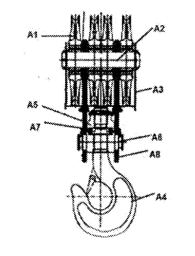
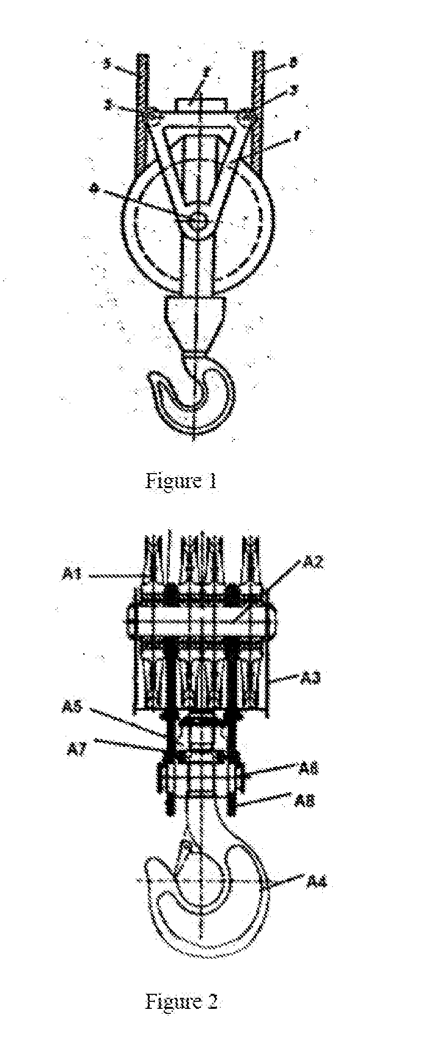
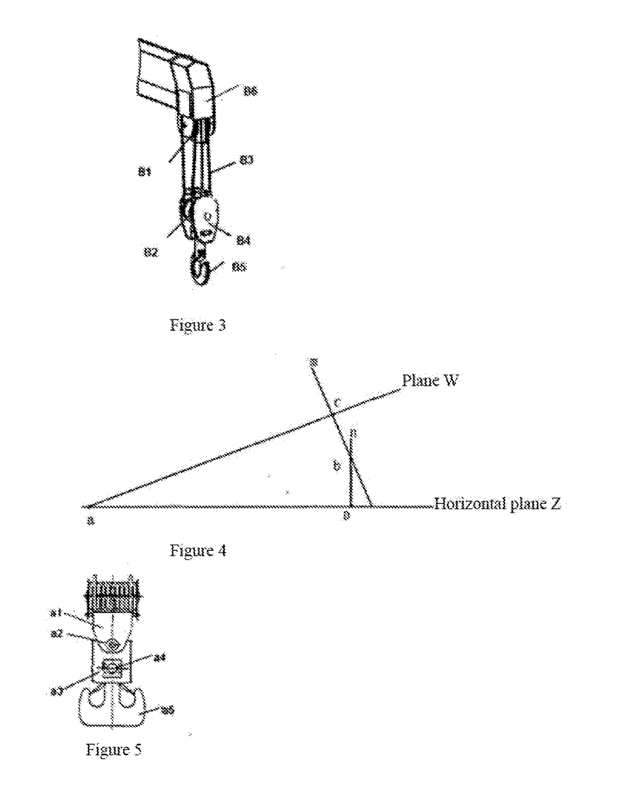
[0050]The mobile crane is equipped with the single pulley block, and clock wisely round-by-round crossing and winding is adopted; the procedures of lifting hook bias angle detection for the mobile crane are as follows: If the hook assembly is equipped with the platform plane perpendicular to the lifting force line of the pulley block, the lifting pulley block lifting force line through the hook is still perpendicular to the installed platform plane when the lifting pulley block is raised and lowered under different bias angles, and then: The included angle between the platform plane and horizontal plane is equal to the bias angle of lifting hook; the orientation of the lifting hook bias angle refers to the one perpendicular to the intersecting line of the platform plane and horizontal plane through the hook, which points to the high end of platform plane, as shown in FIG. 4: The intersecting angle between the...


PUM


Abstract

A lifting hook bias angle monitoring apparatus, a vertical hoisting monitoring apparatus, and a mobile crane. One method is that a lifting hook assembly serially connects connecting plates (b3) provided with hinge connection shafts (b2, b4) at two ends to a movable pulley component (b1) which bears a pulling force and a lifting hook component (b7) which bears a pulling force, and is also provided with a biaxial inclinometer (b9) on a platform surface (b8) of the connecting plates (b3) which is perpendicular to a lifting force line of action of the lifting pulley component, so as to detect a real-time lifting hook bias angle, and accordingly be developed into a mobile crane having a vertical hoisting monitoring function.

Description

CROSS REFERENCE TO RELATED APPLICATIONS[0001]This application is the national phase entry of International Application No. PCT / CN2016 / 094382, filed on Aug. 10, 2016, which is based upon and claims priority to Chinese Application No. CN201610526552.5, filed on Jul. 6, 2016, and Chinese Application No. CN201610629162.0, filed on Aug. 4, 2016, the entire contents of which are incorporated herein by reference.TECHNICAL FIELD[0002]Lifting hook bias angle monitoring apparatus, vertical hoisting monitoring apparatus and mobile crane, which belongs to technical field of crane, actually is a kind of vertical hoisting monitoring apparatus comprising a lifting hook bias angle monitoring apparatus in mobile crane; in other words, it is a mobile crane with vertical lifting monitoring function, including crawler cranes, truck cranes, wheel cranes, all-terrain cranes and lorry-mounted crane.BACKGROUND[0003]If the hoisted state before and after the hoisting is divided into vertical (standing) and h...

Claims


Application Information

Patent Timeline
Patent Type & Authority Applications(United States)
IPC IPC(8): B66C13/16H04N5/268G01B11/26B66C1/34H04N5/225H04N7/18H04N5/232
CPCB66C13/16B66C1/34G01B11/26H04N5/23203H04N5/2253B66C13/06H04N7/185H04N5/23293H04N5/23296B66C1/40H04N5/268B66C13/46B66C15/00H04N23/695B66C1/36H04N23/54H04N23/66H04N23/69
Inventor LIN, HANDING
Owner LIN HANDING
Why Eureka
Try Eureka