Turbine component thermal barrier coating with crack isolating, cascading, multifurcated engineered groove features

a technology of thermal barrier coating and turbine component, which is applied in the direction of machines/engines, stators, liquid fuel engines, etc., can solve the problems of thermal and/or mechanical stress cracking of tbc layer, tbc/turbine component adhesion loss at the interface of dissimilar materials, and the structural integrity of tbc layer, so as to enhance the adhesion of tbc layer

Inactive Publication Date: 2018-01-11
SIEMENS AG
View PDF3 Cites 14 Cited by
  • Summary
  • Abstract
  • Description
  • Claims
  • Application Information

AI Technical Summary

Benefits of technology

[0012]Various embodiments of turbine component construction and methods for making turbine components that are described herein help preserve turbine component thermal barrier coating (“TBC”) layer structural integrity during turbine engine operation. In some embodiments, engineered surface features (ESFs) formed directly in the component substrate or in, intermediate layers applied over the substrate enhance TBC layer adhesion thereto. In some embodiments, the ESFs function as walls or barriers that contain or isolate cracks in the TBC layer, inhibiting additional crack propagation within that layer or delamination from adjoining coupled layers. In some embodiments, the ESFs and vertices of converging EGFs are vertically aligned.

Problems solved by technology

Due to differences in thermal expansion, fracture toughness and elastic modulus,among other things, between typical metal-ceramic TBC materials and typical superalloy materials used to manufacture the aforementioned exemplary turbine components, there is potential risk of thermally- and / or mechanically-induced stress cracking of the TBC layer as well as TBC / turbine component adhesion loss at the interface of the dissimilar materials.
The cracks and / or adhesion loss / delamination negatively affect the TBC layer's structural integrity and potentially lead to its spallation (i.e., separation of the TBC insulative material from the turbine component).
Such cracking loss of TBC structural integrity can lead to further, premature damage to the underlying component substrate.
During continued operation of the turbine engine, it is possible over time that the hot combustion gasses will erode or otherwise damage the exposed component substrate surface, potentially reducing engine operational service life.
Potential spallation risk increases with successive powering on / off cycles as the engine is brought on line to generate electrical power in response to electric grid increased load demands and idling down as grid load demand decreases.
In addition to thermal- or vibration-induced, stress crack susceptibility, the TBC layer on engine components is also susceptible to foreign object damage (“FOD”) as contaminant particles within the hot combustion gasses strike the relatively brittle TBC material.
A foreign object impact can crack the TBC surface, ultimately causing spallation loss of surface integrity that is analogous to a road pothole.
Once foreign object impact spalls off a portion of the TBC layer, the remaining TBC material is susceptible to structural crack propagation and / or further spalling of the insulative layer.
In addition to environmental damage of the TBC layer by foreign objects, contaminants in the combustion gasses, such as calcium, magnesium, aluminum, and silicon (often referred to as “CMAS”) can adhere to or react with the TBC layer outer surface, increasing the probability of TBC spallation and exposing the underlying BC.
In order to enhance TBC layer structural integrity and affixation to turbine component underlying substrates, past attempts have included development of stronger TBC materials better able to resist thermal cracking or FOD, but with tradeoffs in reduced thermal resistivity or increased material cost.

Method used


Image

  • Turbine component thermal barrier coating with crack isolating, cascading, multifurcated engineered groove features
  • Turbine component thermal barrier coating with crack isolating, cascading, multifurcated engineered groove features
  • Turbine component thermal barrier coating with crack isolating, cascading, multifurcated engineered groove features

Examples


Embodiment Construction

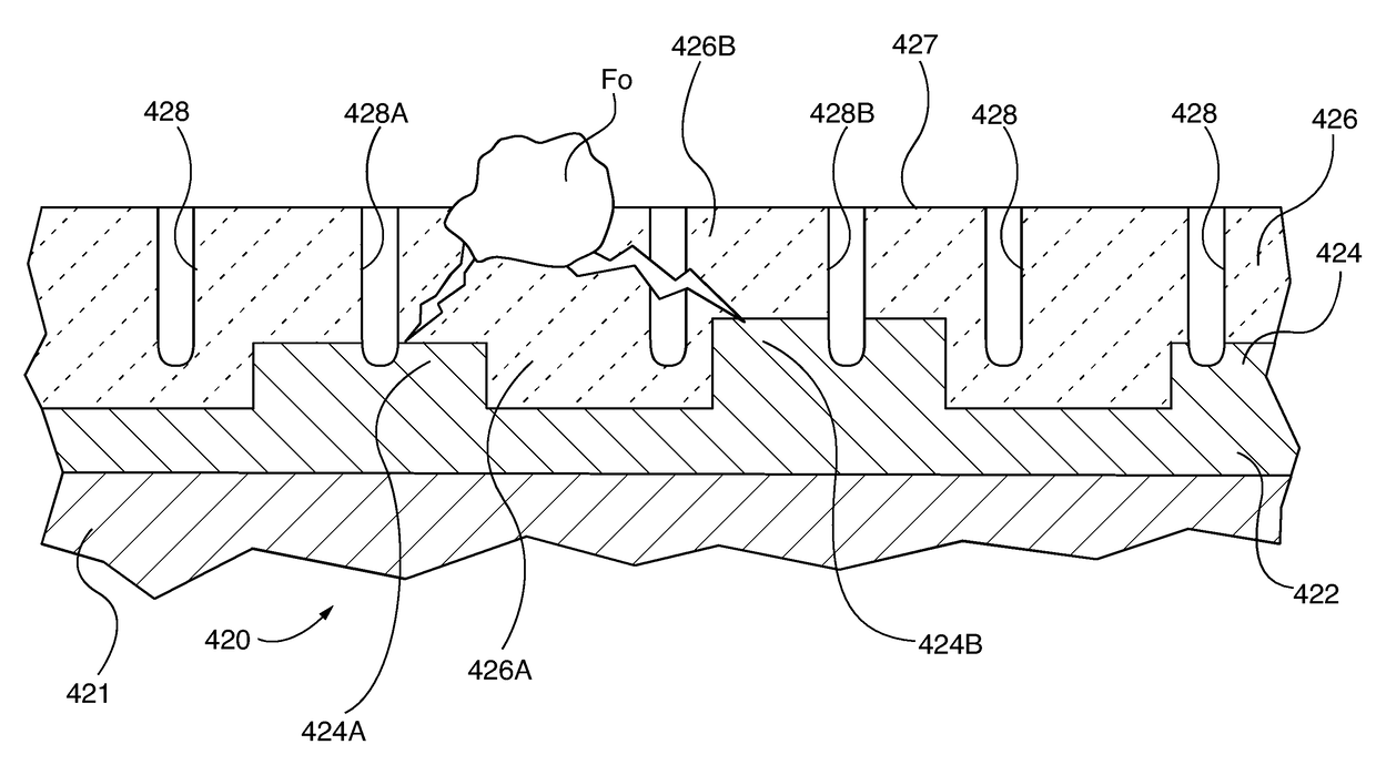
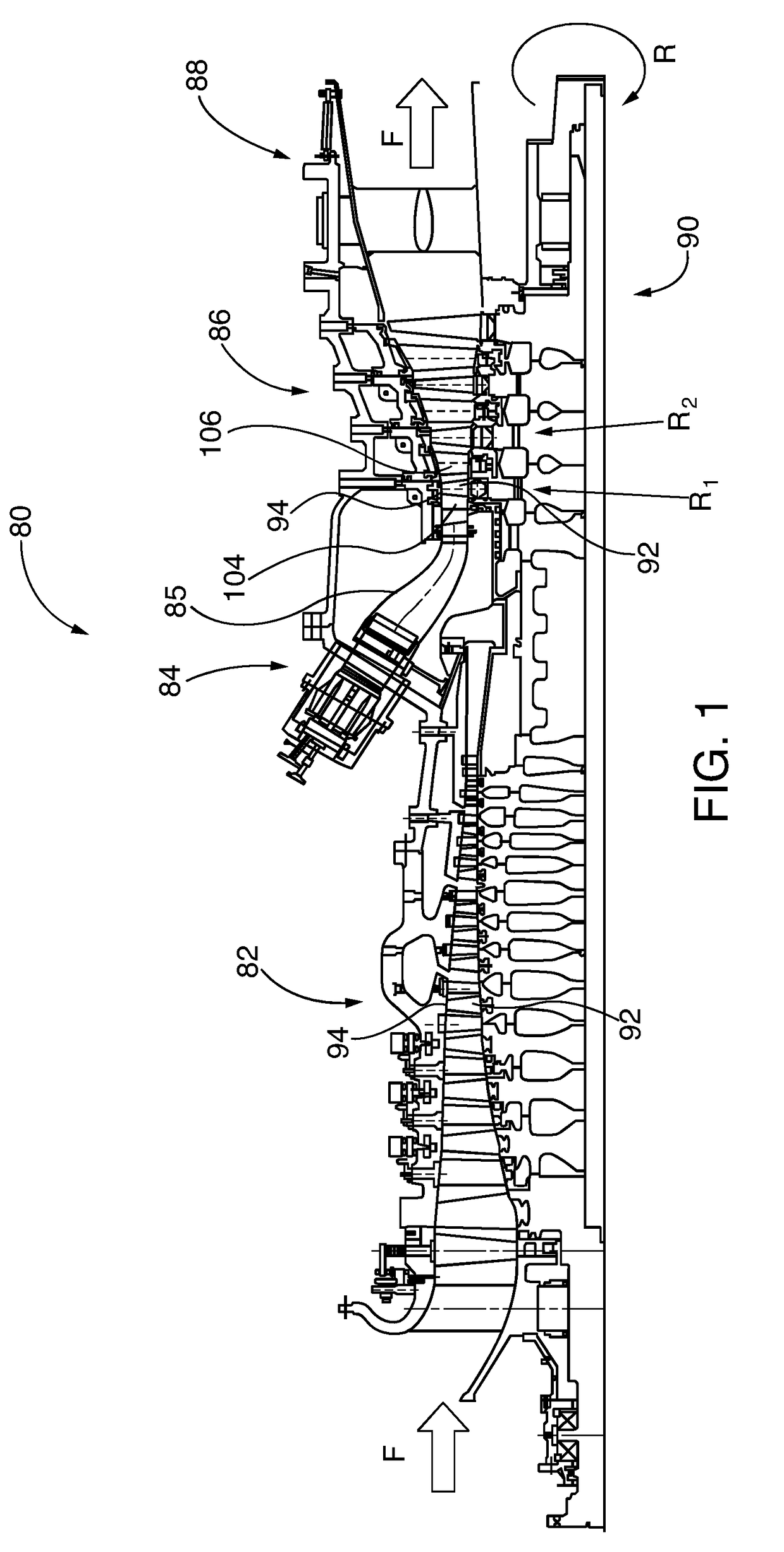
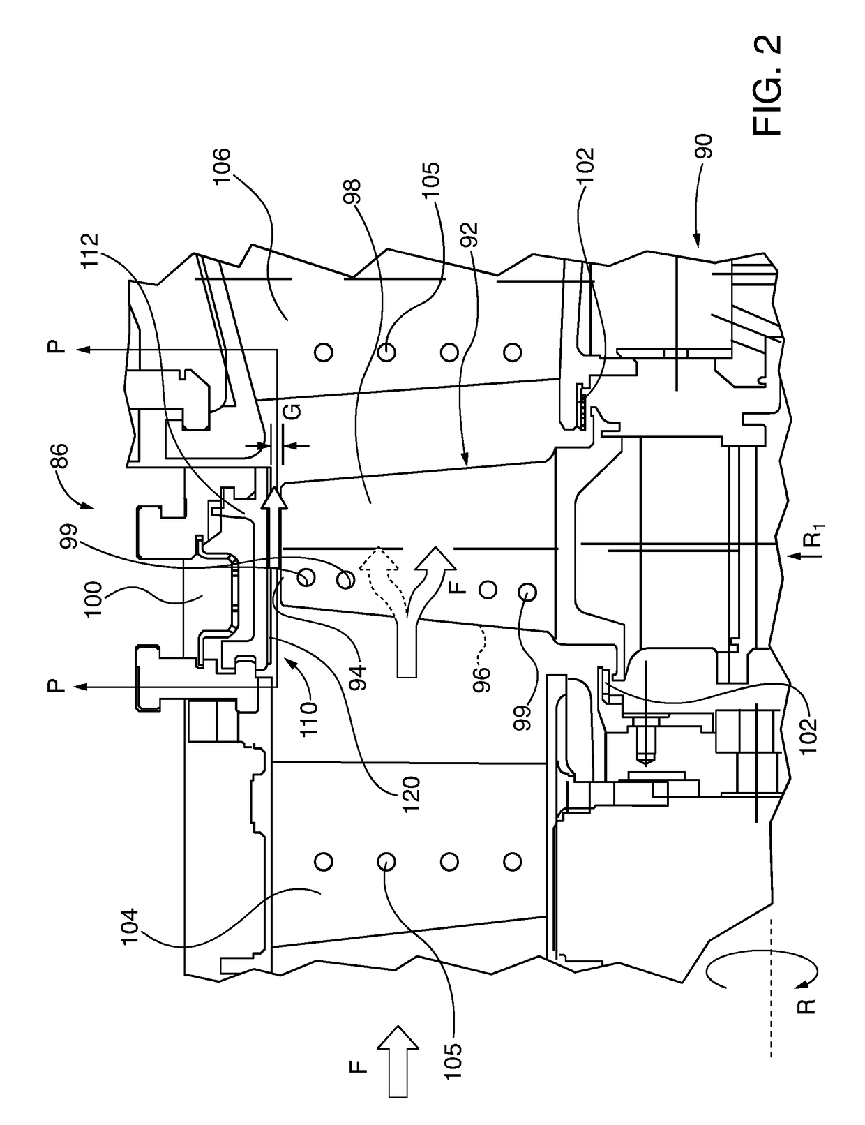
[0062]Exemplary embodiments of the present invention enhance performance of the thermal barrier coatings (“TBCs”) that are applied to surfaces of turbine engine components, including combustion or gas turbine engines, as well as steam turbine engines. In exemplary embodiments of the invention that are described in detail herein, engineered groove features (“EGFs”) are formed within the TBC, and more particularly in the outer surface of the TBC. In the case of multi-layer TBC applications, the EGFs are formed in the outer surface of the outer thermal barrier coating (“OTBC”), and selectively are cut to any desired depth, including down to the substrate surface. EGF widths are also selectively varied. The EGFs are formed in furcated planform patterns, meaning multiple grooves converge, or from another alternative relative perspective, diverge in a forked pattern from a common vertex. In embodiments where three grooves converge at a vertex, they are arrayed in a bifurcated pattern, mea...


PUM

PropertyMeasurementUnit
combustion temperaturesaaaaaaaaaa
thicknessaaaaaaaaaa
thicknessaaaaaaaaaa

Abstract

Turbine engine (80) components, such as blades (92), vanes (104, 106), ring segment 110 abradable surfaces 120, or transitions (85), have furcated engineered groove features (EGFs) (403, 404, 418, 509, 511, 512) that cut into the outer surface of the component's thermal barrier coating (TBC). In some embodiments, the EGF planform pattern defines adjoining outer hexagons (560, 640, 670, 690, 710). In some embodiments, the EGF pattern further defines within each outer hexagon (560, 640, 670, 690, 710) a planform pattern of adjoining inner polygons (570, 580, 590, 600, 610, 680, 682, 700, 702, 704, 705, 720). At least three respective groove segments (509, 511, 512) within the EGF pattern (506, 507, 508) converge at each respective outer hexagonal vertex (510, 564) or inner polygonal vertex (574, 564, 604, 614) in a multifurcated pattern, so that crack-inducing stresses are attenuated in cascading fashion, as the stress (σA) is furcated (σB, σC) at each successive vertex juncture.

Description

PRIORITY CLAIM AND CROSS-REFERENCE TO RELATED APPLICATIONS[0001]This application claims priority under the following International Patent Applications, the entire contents of each of which is incorporated by reference herein:[0002]“TURBINE COMPONENT THERMAL BARRIER COATING WITH CRACK ISOLATING ENGINEERED GROOVE FEATURES”, filed Feb. 18, 2015, and assigned application number PCT / US2015 / 016318; and[0003]“TURBINE COMPONENT THERMAL BARRIER COATING WITH CRACK ISOLATING ENGINEERED SURFACE FEATURES”, filed Feb. 18, 2015, and assigned application number PCT / US2015 / 016331.[0004]A concurrently filed International Patent Application entitled “TURBINE COMPONENT THERMAL BARRIER COATING WITH VERTICALLY ALIGNED, ENGINEERED SURFACE AND MULTIFURCATED GROOVE FEATURES”, docket number 2015P22738WO, and assigned serial number (unknown) is identified as a related application and is incorporated by reference herein.TECHNICAL FIELD[0005]The invention relates to combustion or steam turbine engines having th...

Claims


Application Information

Patent Timeline
Patent Type & Authority Applications(United States)
IPC IPC(8): F01D5/28F01D5/14F01D11/12
CPCF01D5/288F01D5/147F01D11/122F05D2230/312F05D2230/313F05D2230/90F05D2250/132F05D2250/294F05D2250/60F05D2300/502F01D11/08F01D11/12F01D5/14F01D5/18F01D5/186F01D5/28Y02T50/60C23C4/134C04B41/81C04B41/91C23C16/045F01D5/282F01D9/023F04D29/324F04D29/542F04D29/5853F05D2220/32F05D2230/10F05D2240/35F05D2300/5023F05D2300/6033
Inventor KADAU, KAIPASCUAL-GUTIERREZ, JOSE ANTONIOSHARMA, ATIN
Owner SIEMENS AG
Why Eureka
Try Eureka