Buried sensor system

a sensor and wire technology, applied in the field of buried sensor systems, can solve the problems of burdensome battery replacement or cost, and the cost of providing power to the network of buried sensors through buried wires,

Active Publication Date: 2018-01-11
RAYTHEON BBN TECH CORP
View PDF7 Cites 3 Cited by
  • Summary
  • Abstract
  • Description
  • Claims
  • Application Information

AI Technical Summary

Benefits of technology

[0004]Aspects of embodiments of the present disclosure are directed toward a sensing system including in-ground sensors not requiring battery power. A thermoelectric generator sensor rod includes an upper thermal contact and a lower thermal contact at or near its two ends. When the thermoelectric generator sensor rod is buried in the ground with one end buried more deeply than the other, a temperature gradient in the soil produces a ...

Problems solved by technology

Providing power to a network of buried sensor via buried wires may be costly.
Some related art sensors may be battery powere...

Method used


Image

  • Buried sensor system
  • Buried sensor system
  • Buried sensor system

Examples


Embodiment Construction

[0035]The detailed description set forth below in connection with the appended drawings is intended as a description of exemplary embodiments of a buried sensor system provided in accordance with the present invention and is not intended to represent the only forms in which the present invention may be constructed or utilized. The description sets forth the features of the present invention in connection with the illustrated embodiments. It is to be understood, however, that the same or equivalent functions and structures may be accomplished by different embodiments that are also intended to be encompassed within the spirit and scope of the invention. As denoted elsewhere herein, like element numbers are intended to indicate like elements or features.

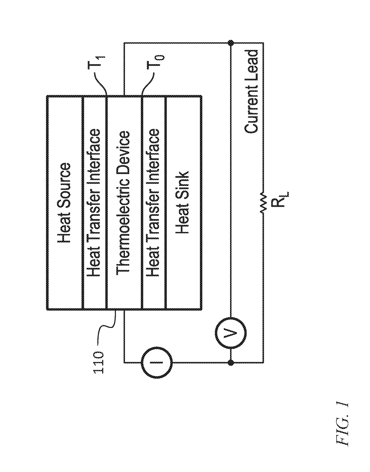
[0036]Referring to FIG. 1, in one embodiment, a sensor system includes a power source that generates electrical power using a temperature difference between a heat source at a first temperature and a heat sink at a lower temperature. Ea...


PUM


Abstract

A sensing system including in-ground sensors not requiring battery power. A thermoelectric generator sensor rod includes an upper thermal contact and a lower thermal contact at or near its two ends. When the thermoelectric generator sensor rod is buried in the ground with one end buried more deeply than the other, a temperature gradient in the soil produces a temperature difference between the upper thermal contact and the lower thermal contact. The upper thermal contact and the lower thermal contact are thermally connected to a thermoelectric generator, e.g., by heat pipes or thermally conductive rods. Electrical power generated by the thermoelectric generator powers sensors for monitoring conditions in the ground, and circuitry for transmitting sensor data to a central data processing system.

Description

BACKGROUND1. Field[0001]One or more aspects of embodiments according to the present invention relate to in-ground sensing systems, and more particularly to an in-ground sensing system not requiring battery power.2. Description of Related Art[0002]Numerous commercial and military applications exist for sensors that monitor various quantities from within the ground. Examples include sensors monitoring soil conditions (e.g., moisture, temperature, pH, or the abundance of certain chemicals) or sound or vibration sensors e.g., for detecting the passage of vehicles. Such sensors may use electrical power. Providing power to a network of buried sensor via buried wires may be costly. Some related art sensors may be battery powered; battery powered sensors, however, may have the disadvantage that replacing or recharging batteries may be burdensome or costly.[0003]Thus, there is a need for an in-ground sensor system that does not require batteries for power.SUMMARY[0004]Aspects of embodiments ...

Claims


Application Information

Patent Timeline
IPC IPC(8): H01L35/10H01L35/16H01L35/30H01L35/32
CPCH01L35/10H01L35/32H01L35/30H01L35/16F24T10/00Y02E10/10H10N10/82H10N10/852H10N10/17H10N10/13
Inventor INSANIC, EDINCOCHIN, JOSHUAJORDAN, ALEX BENJAMIN
Owner RAYTHEON BBN TECH CORP
Why Eureka
Try Eureka