Plexus of Filaments with Linked Members

Active Publication Date: 2018-01-25
JAMISON BRADFORD C
View PDF1 Cites 65 Cited by
  • Summary
  • Abstract
  • Description
  • Claims
  • Application Information

AI Technical Summary

Benefits of technology

[0020]An end use of a plexus of filaments as described herein, would be the production of a human body resting devise, wherein the invention would be produced as a tubular or flat plexus of filaments, and would then be tensioned around a frame. The advantage of such a device would be not only to provide a breathable mesh, but also to equally distribute the load from pressure points, which engage the material, which would then improve circulation at typical pressure points on a human body while at rest.
[0021]Aspects of the present invention may be applied to a broad range of industries and technologies. For example, another end use for material produced by the present invention would include apparel and accessories, which could be produced at least partially, from

Problems solved by technology

This has generally been due to the limitations of standard braiding machines currently utilized in the marketplace.
In fact, most braiding machines are only capable of producing standard biaxial braids.
As recognized by the present inventor, conventional means of weaving and braiding of yarns, threads, and other filamentous material can yield less than ideal products, especially due to the non-conforming nature of woven and braided material, which typically relies on friction and filament proximities to retain filament network uniformity.
Another limitation in prior art weaves and braids is due to the primarily linear, taunt nature of the filaments within a plexus.
Another limitation of weaves and braids is their ability to absorb impact, insomuch that woven filaments, function primarily as singular filaments, and not as a

Method used


Image

  • Plexus of Filaments with Linked Members
  • Plexus of Filaments with Linked Members
  • Plexus of Filaments with Linked Members

Examples


Example

DETAILED DESCRIPTION OF DRAWINGS

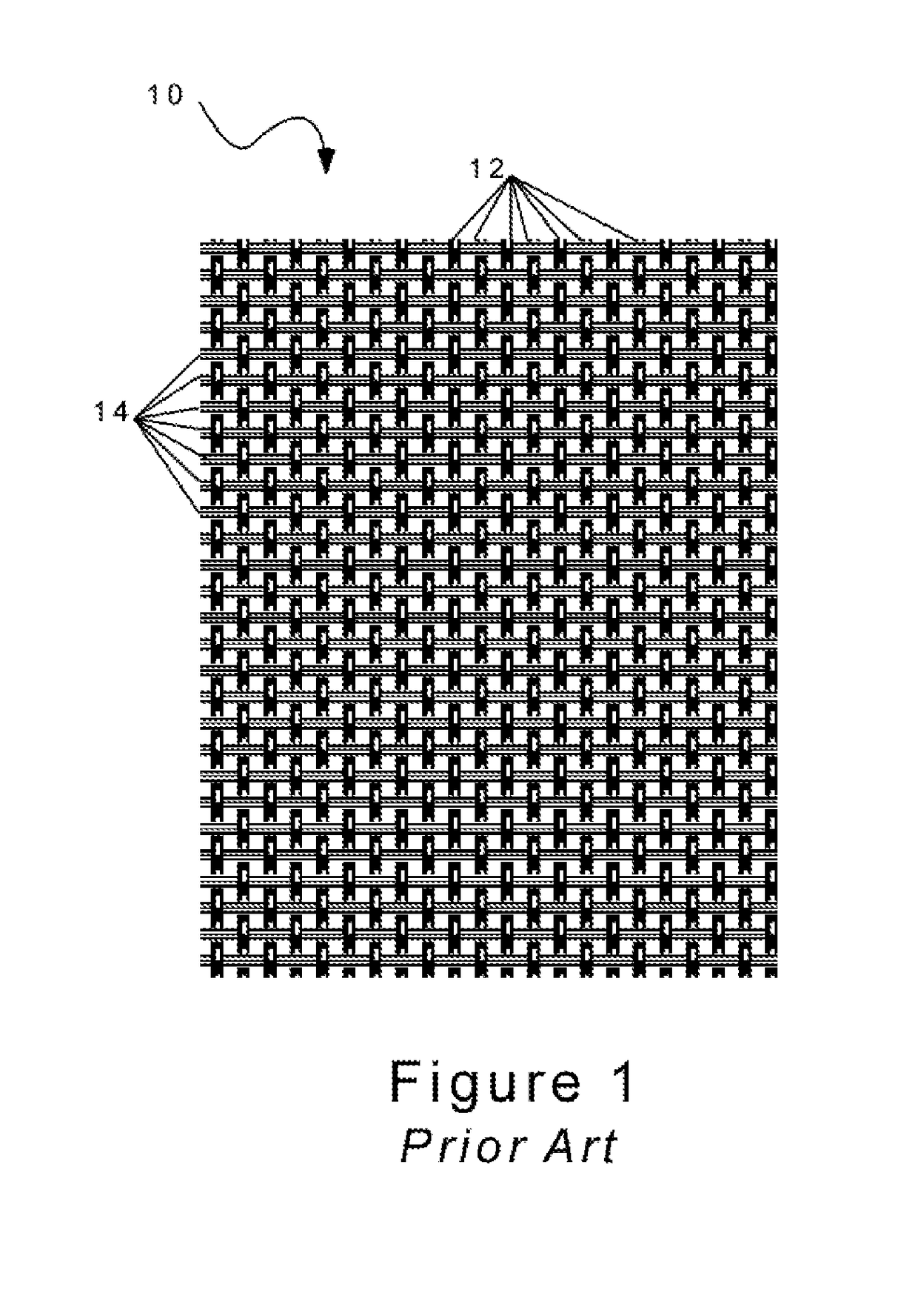
[0033]FIG. 1 is a schematic illustration of woven filaments 10, as described by prior art. As shown in FIG. 1, and as is typical of woven filament structures, weave pattern 10 typically includes a series or plurality of longitudinal or vertical “warp” filaments 12 traversing along the zero degree axis which perpendicularly engage with a plurality of lateral or horizontal “weft” filaments 14 which traverse along the 90 degree axis. As shown, warp filaments 12“interlace”; cross in front and behind; weft filaments 14, for example, the patterned behavior of the filaments is to first pass over a filament and then under the next filament, and repeat this patterned process with a plurality of regularly spaced perpendicular filaments. As know in the art, the close proximity of the warp filaments 12 and weft filaments 14, is what provides the structural integrity, or integration of the fibers into one plexus of material 10; primarily through the friction betwe...


PUM


Abstract

Disclosed herein is a plexus of filaments which is composed of paired filaments which travel extensively around one another to form a double helix structure, where each pair of filaments belongs to a group of filaments, traverse at crossing angles to other filaments which belong to at least another group of filaments, thus repetitively crossing the paths of the filament pairs in at least another group of filaments. Also defined within the specifications and claims herein is the linking of the filaments between the different paired groups of filaments, which facilitates the distribution of tension between the filaments within a plexus of filaments. Herein described are plexuses which exhibit greater conformal and constrictive qualities in comparison to the prior art. Also disclosed is a method of producing filament structures for a variety of uses including composite structures, with enhanced structural properties, including but not limited to; tension displacement properties, for use in applications requiring conformal load distribution with minimal weight.

Description

CROSS-REFERENCE TO RELATED APPLICATIONS[0001]This application claim priority from U.S. Provisional Patent Application 62 / 364,058 filed on Jul. 19, 2016, the disclosures of which are included by reference herein in their entirety.BACKGROUND OF THE INVENTIONTechnical Field[0002]The present invention generally relates to a plexus of strands, or braided filaments, threads, yarns etc., and the processes and apparatus for forming plexuses, or fabrics from yarns, filaments or strands, by interlacing and linking filaments or strands, to produce fabrics and / or products produced from filament plexuses. The present invention more specifically relates to unique patterns that can be produced on machines that can be programmed to produce a unified plexus of filaments; for use in any number of applications; whether those applications utilize the fabrics with, or without a matrix, such as a polymer, to form a composite structure.[0003]As an untreated “dry” plexus of fibers, the patterned filaments ...

Claims


Application Information

Patent Timeline
IPC IPC(8): A43B1/04D04C1/10D04C1/02A43B23/04
CPCA43B1/04A43B23/042D10B2501/043D04C1/02D03D13/002D04C1/10A43B23/0205
Inventor JAMISON, BRADFORD C.
Owner JAMISON BRADFORD C
Why Eureka
Try Eureka