High load steerable shaft and method for cardiac catheter

a catheter and high-load technology, applied in the direction of catheters, guide wires, etc., can solve the problems of kink resistance and axial stiffness of the deflection section, the difficulty of reaching the heart area, and the difficulty of treating using a catheter, so as to achieve high actuation load and enhance kink resistance and axial stiffness

Active Publication Date: 2018-01-25
CREGANNA UNLTD
View PDF2 Cites 9 Cited by
  • Summary
  • Abstract
  • Description
  • Claims
  • Application Information

AI Technical Summary

Benefits of technology

[0010]The present invention provides a steerable device for a catheter that includes a hollow tube of generally circular cross section containing a metal support structure to provide enhanced kink resistance and axial stiffness. The support structure can be arranged to allow movement in one or more defined directions. The support structure can also provide an anchorage, or anchor site, for an articulation system which is capable of transmitting high actuation loads to the device.

Problems solved by technology

Access to the patient's anatomy and deliverability of the treatments continue to be primary challenges of the devices.
These areas of the heart are difficult to reach and difficult to treat using a catheter.
However, the softer the deflection section material is the more likely the deflection section is to kink and for the sheath as a whole to shrink axially.
Increasing the hardness of the material in the deflection section of the catheter leads to higher actuation forces being required to deflect the sheath itself, putting strain on the actuation mechanism, especially at the actuator to distal end attachment of the wire.
Increasing the thickness of the material also leads to higher actuation forces and results in a thicker sheath wall.
The thicker sheath wall is not ideal as this takes up limited space.
Increasing the density of the reinforcement material can also have a negative impact on wall thickness and actuation forces.

Method used


Image

  • High load steerable shaft and method for cardiac catheter
  • High load steerable shaft and method for cardiac catheter
  • High load steerable shaft and method for cardiac catheter

Examples


Embodiment Construction

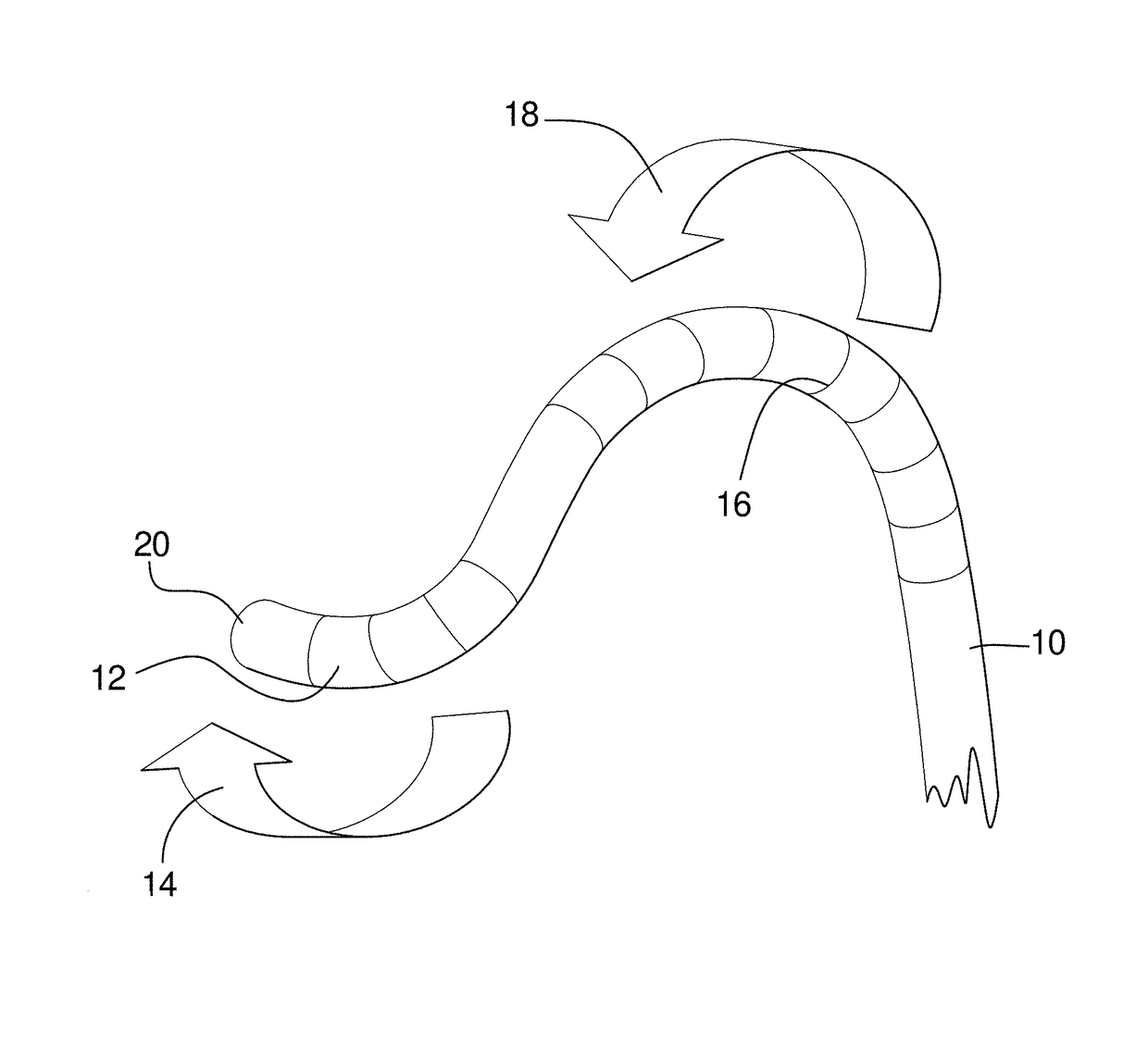
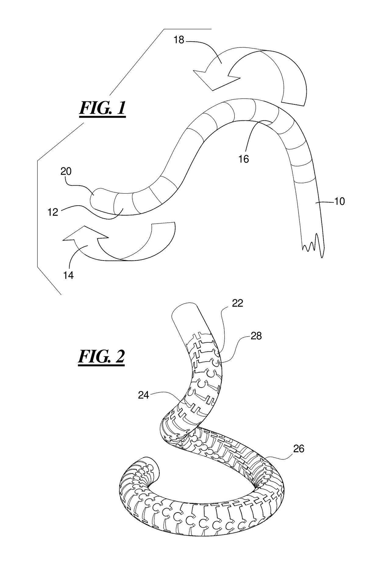
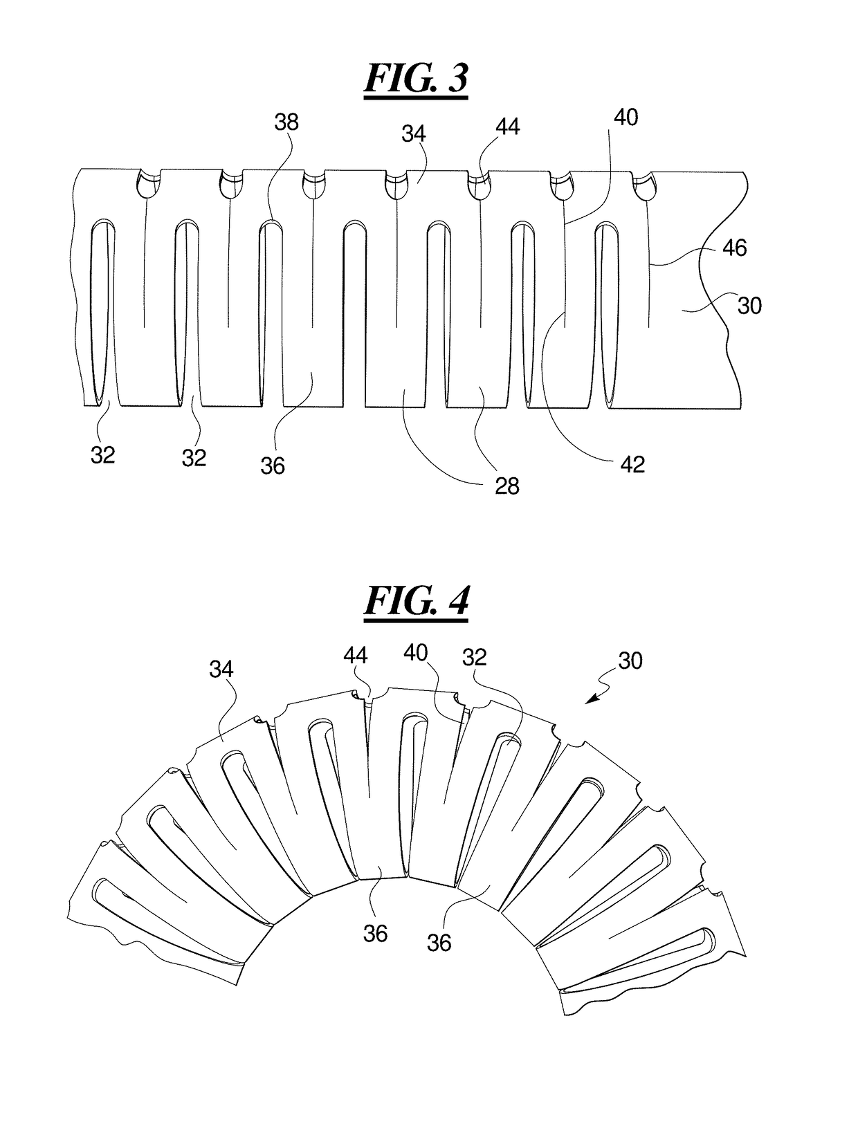
[0024]The present apparatus includes a reinforcing structure or skeleton that is constructed to be stiff in an axial direction but flexible in one or several non-axial directions. The reinforcing structure or skeleton may include a cut metal tube, a formed wire structure, or other reinforcing structure. For example, the cut metal tube may include a laser cut metal tube. The reinforcing structure or skeleton may include hinge structures that permit flexing in at least one direction but that provide axial stiffness to the reinforcing structure. In certain embodiments, the reinforcing structure or skeleton is formed to flex in different bending directions at different bending locations.

[0025]The cut metal tube, skeleton, or other reinforcing structure is assembled into a distal / deflectable section of a sheath, over a liner if required, and is jacketed by a polymer material. Pull cables or actuator cables are threaded through lumens inside the cut metal tube, skeleton or other reinforci...


PUM


Abstract

A tube or skeleton for a steerable catheter includes a cylindrical body structured to permit bending in at least one bending direction and to resist bending in directions transverse to the bending direction. The cylindrical body may include a laser cut metal tube, wires bent and connected to one another, or one or more coiled wires with axial support wires attached to the coil to define one or more bending directions to form bending segments. The skeleton includes axially stiff portions that resist compression when a pull wire is pulled to cause bending movement. The axially stiff portions may include a backbone, an alignment of pivot structures, connected axially extending portions of wire elements, or axially extending support wires or rods. Two or more bending portions may be provided, each with different bending directions. Complex bending shapes may be provided by arranging the segments in rotated positions along the skeleton.

Description

CROSS REFERENCE TO RELATED APPLICATION[0001]The present application claims the benefit of U.S. Provisional Patent Application Ser. No. 62 / 365,044, filed on Jul. 21, 2016, which application is incorporated herein by reference.BACKGROUND OF THE INVENTIONField of the Invention[0002]The present invention relates generally to an apparatus and method for a catheter, and more particularly to an apparatus and method for a steerable cardiac catheter.Description of the Related Art[0003]As percutaneous treatments for structural heart diseases continue to evolve, new devices for treatment of both acquired and congenital diseases are becoming available. Access to the patient's anatomy and deliverability of the treatments continue to be primary challenges of the devices. Specifically the nature of the cardiac anatomy and the large diameter of the devices being delivered combine to create these challenges.[0004]The complex structure of cardiac anatomy must be addressed, for example when tracking u...

Claims


Application Information

Patent Timeline
Patent Type & Authority Applications(United States)
IPC IPC(8): A61M25/01A61M25/09
CPCA61M25/0144A61M25/09033A61M25/09A61M25/0133A61M2025/09175A61M25/0138A61M25/0147A61M2025/0161
Inventor MCDERMOTT, BERNARDSZCZEPANSKI, ADAM
Owner CREGANNA UNLTD
Why Eureka
Try Eureka