Bending and molding production line

a technology applied in the field of bending and molding production lines, can solve the problems of low machining efficiency, low precision, and low production efficiency of existing such types of devices, and achieve the effects of reducing vibration generated during bending, stable bending, and improving the working reliability of the whole devi

Active Publication Date: 2018-01-25
JIANGSU UNIV OF SCI & TECH +1
View PDF3 Cites 29 Cited by
  • Summary
  • Abstract
  • Description
  • Claims
  • Application Information

AI Technical Summary

Benefits of technology

[0022]Since the clamping component of the clamping device is driven by the cylinder, such that in the bending process, the tubular product is stably bent, the vibration generated during bending is reduced, and the working reliability of the whole device is improved.
[0023]Since the hollow shaft is provided with the moving bending head, the mandrel is detachably provided with the fixed bending die, and the central shaft and the mandrel are respectively driven by an external power connecting device, the whole structure is simple and convenient to mount.
[0024]Since the transmission mechanism of the central clamping device comprises the left transition gear and the right transition gear which are disposed at two sides of the reset oil cylinder in the box body and meshed with the rotary gear disk respectively, due to a driving manner of the two transition gears, the rotation of the rotation gear disk is more stable, a rotation error possibly caused by a gear side gap in a forward and backward rotation process due to the driving from single side gears is avoided, such that the device is higher in rotation precision, error accumulation is avoided, and therefore, the bending quality of the tubular product is improved; and the driving of the synchronous belt and the synchronous belt wheel is adopted, such that the advantages of buffering and damping, stable transmission and convenience in maintenance are realized.
[0025]The clamping mechanism adopts a spring self-clamping structure, and is simple in structure and stable in clamping force, the oil cylinders are only disposed in the charging position and poking position, the clamping mechanism can be only opened by push of the piston

Problems solved by technology

But since the bending precision of the tubular product is low or a residual stress is overlarge, a workpiece is failed, which leads to a loss of social properties.
However, the existing such type of devices difficultly constitute an automatic bending production line with a high precision and a high production efficiency.
Firstly, a traditional single-head bending device is lower in efficiency due to a lower bending speed. At present, some dual-head bending devices are emerged on the market, but most of the existing dual-head bending mechanisms can realize symmetric bending instead of asymmetric machining, and the machining efficiency is low; meanwhile, the maintenance of a power part is large in mounting and dismounting work amount, efficient replacement and maintenance are hard to realize, and a low working efficiency is caused. For example, the patent with a patent number 201020147236.5 discloses a tube bending machine, a bending device thereof can realize symmetric bending only and cannot provide the machining of asymmetric tubes and tubular products. For example, the patent with a patent number 201020595165.5, discloses a tube bending machine, a power part of a bending device thereof is relatively complex to mount and dismount, and efficient maintenance is hard to realize,

Method used


Image

  • Bending and molding production line
  • Bending and molding production line
  • Bending and molding production line

Examples


Embodiment Construction

[0056]Specific implementing solutions of the present invention are described in detail in combination with the drawings.

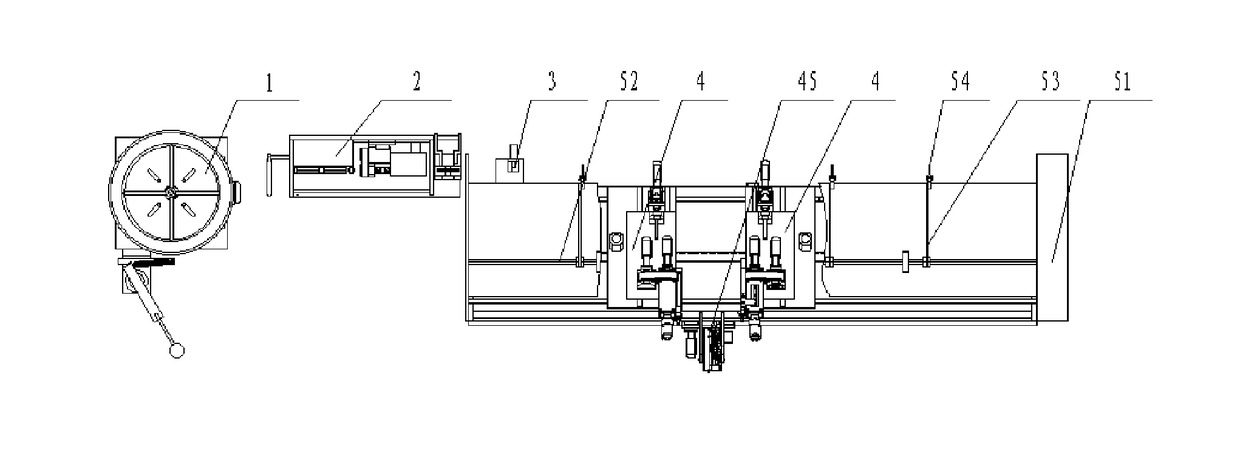
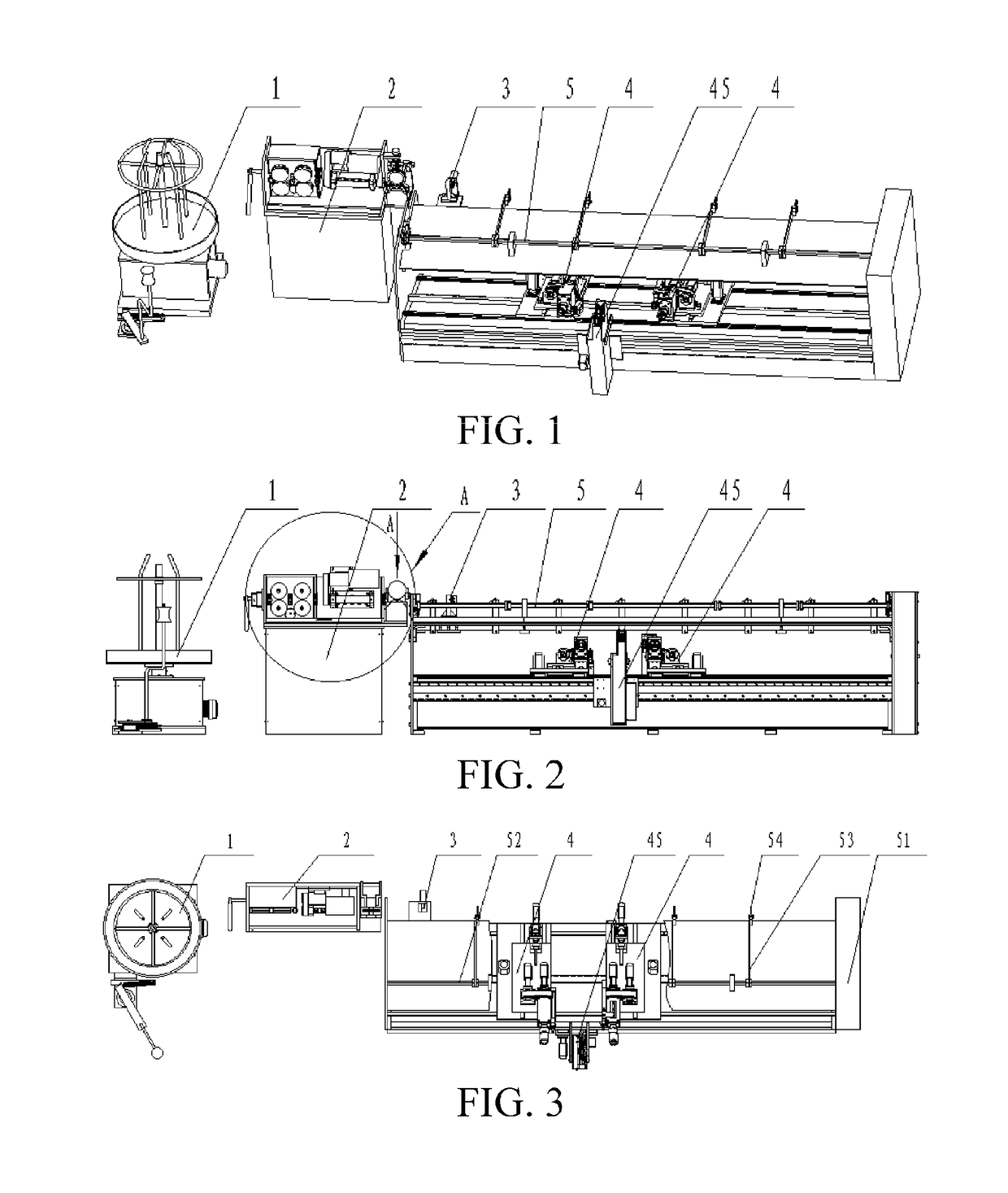
[0057]As shown in FIGS. 1-3, a bending and molding production line comprises an unwinding mechanism 1, a feeding and straightening device 2, a cutting-off mechanism 3, a bending and molding device 4 and a material loading mechanism 5 for transferring the tubular product to the bending and molding device from the cutting-off mechanism.

[0058]As shown in FIGS. 8-11, the unwinding mechanism 1 comprises a box type base 11, a motor 12 and a speed reducer 13 connected to the motor 12 are disposed in the base 11, a material disc 14 is rotatably disposed on the base 11, the speed reducer 13 drives the material disc 14 to rotate, the material disc 14 is provided with a central rod 15 coaxial with an output shaft of the speed reducer 13, the material disc 14 is provided with at least three blocking rods 16, the blocking rods 16 are uniformly distributed around the central rod...


PUM

PropertyMeasurementUnit
Angleaaaaaaaaaa
Shapeaaaaaaaaaa
Radiusaaaaaaaaaa

Abstract

The present invention discloses a bending and molding production line, comprising an unwinding mechanism, a feeding and straightening device, a cutting-off mechanism, a bending and molding device and a material loading mechanism, wherein the bending and molding device comprises a base, the base is provided with two transverse sliding bases, the base is provided with a transverse driving device driving the transverse sliding bases, the base is provided with a central clamping device between the two transverse sliding bases, the transverse sliding bases are provided with a longitudinal sliding base in a sliding manner and are provided with a longitudinal driving device driving the longitudinal sliding base to slide, the longitudinal sliding base is provided with a bending and molding device, one side, close to the central clamping device, of the transverse sliding base at the left side is provided with a left clamping device capable of movably extending to clamp the tubular product, and one side, close to the central clamping device, of the transverse sliding base at the right side is provided with a right clamping device capable of movably extending to clamp the tubular product. The production line can bend two sides of a tubular product or a wire stock by different bending angles and different bending radii, and the working efficiency is high.

Description

BACKGROUNDTechnical Field[0001]The present invention relates to a bending and molding production line.Related Art[0002]For the bending and molding production line of a tubular product such as an air conditioner tube and an engine oil tube, a tubular product coil material is required to be straightened into a material with certain straightness, and is then bent and molded. At present, such bent tubular product is widely applied to the field of engines, in particular an oil path in an aerospace airspace engine, a ship engine and a vehicle engine. But since the bending precision of the tubular product is low or a residual stress is overlarge, a workpiece is failed, which leads to a loss of social properties.[0003]A complete tubular product automatic bending production line comprises an unwinding mechanism, a feeding and straightening device, a cutting-off mechanism, a bending and molding device and a material loading mechanism for transferring the tubular product to the bending and mol...

Claims


Application Information

Patent Timeline
IPC IPC(8): B21D35/00B21F1/02B21D7/08
CPCB21D35/002B21D7/08B21F1/026B21D35/00B21D7/024B21D7/16B21F1/00
Inventor TANG, WENXIANZHANG, JIANLIN, HONGCAIZHANG, YANGLI, QINFENGTAO, ZHIGAOLI, XIAWANG, SHUYAN
Owner JIANGSU UNIV OF SCI & TECH
Why Eureka
Try Eureka