Die for bending press forming

A stamping forming and mold technology, applied in the field of bending stamping molds, can solve the problems of increased processing times, increased manufacturing costs, difficult and efficient manufacturing, etc.

Active Publication Date: 2019-01-29
JFE STEEL CORP
View PDF8 Cites 0 Cited by
  • Summary
  • Abstract
  • Description
  • Claims
  • Application Information

AI Technical Summary

Problems solved by technology

[0009] However, with this bending method, the number of times of processing increases, making it difficult to efficiently manufacture. As a countermeasure for this, for example, Patent Document 1 proposes a method in which, during press forming in the width direction of a steel sheet, At both end portions in the width direction of the steel plate and at a specified middle portion, straight portions of desired lengths are left, and the straight portions are bent to form arcuate portions, and the seam portions are welded. To form a semi-formed round steel pipe, after heating the whole of the semi-formed round steel pipe, make its forming surface pass between a plurality of semi-circular forming rollers corresponding to the final radius to perform thermoforming, thereby adjusting the shape
[0010] However, the method disclosed in the above-mentioned Patent Document 1 has the following problem: the molded body after press forming has a shape close to a quadrilateral, and it is necessary to separately provide a process for correcting the shape (heating process). volume will lead to a significant increase in manufacturing costs
However, since the rotation support is smaller than the width of the curved plate, there is a concern that a large surface pressure will act on this part, causing wear and deformation of the rotation support, and the rotation function may not be maintained in the early stage.

Method used


Image

  • Die for bending press forming
  • Die for bending press forming
  • Die for bending press forming

Examples


Embodiment

[0069] Prepare nine steel plates (steel type: API grade. X80) with a dimension of 3713mm along the feeding direction of the plate S, a plate thickness of 25.4mm, and a tensile strength of 745-757Mpa. Both end portions of each were bent so as to form an angle of 16.9 degrees within a range of 215 mm.

[0070] Next, take the position 1492 mm away from the center of the steel plate (the center of the dimension along the feed direction) on one side as the processing starting point, and set the feed pitch at 298 mm / time, the amount of bending forming at 29.6° / time, and the number of times of punching Three-point bending was performed from the left and right sides toward the center of the steel plate under the condition of five times.

[0071] In addition, the steel plate subjected to three-point bending was further subjected to one three-point bending (a total of eleven bendings) at the center, and after the interval between the butting portions of both ends of the steel plate was ...


PUM

PropertyMeasurementUnit
thicknessaaaaaaaaaa
tensile strengthaaaaaaaaaa
thicknessaaaaaaaaaa

Abstract

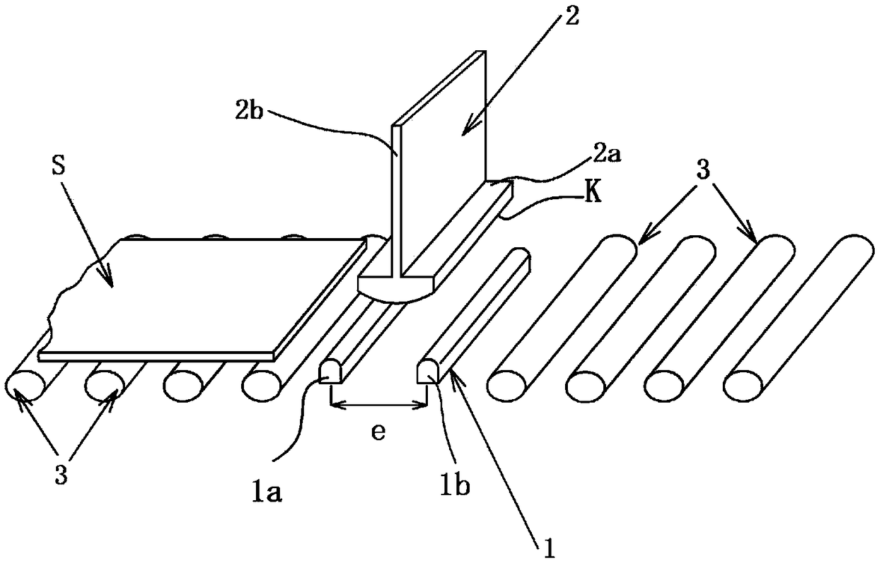
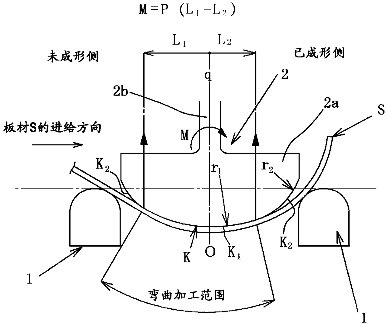
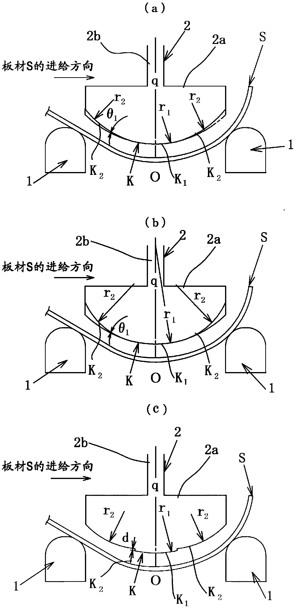
A die for bending press forming capable of reducing the influence of bending moment and obtaining a cylindrical body with high roundness is proposed. The bending stamping die has: a pair of left and right dies (1), which support the sheet material (S) at two places; and a punch (2), which can move toward and away from the die (1), and Bending is carried out by sequentially pressing the plate (S) along its width direction while being pinched by the die (1), and the punch (2) is supported by the punch tip (2a) and the punch in the bending press forming die body (2b), wherein the front end of the punch (2a) has a processing surface (K) that is in direct contact with the sheet (S) to press the sheet (S) into a concave shape, and the punch support (2b) and the punch The front end (2a) is connected and held to support the punch front end (2a). In addition, a processing surface (K) having a processing center (O) coincident with the axis (q) of the punch support body (2b) is provided on the punch front end (2a), and is formed by A non-uniform arc is formed with the radius at the central region in the width direction of the punch tip portion set to the maximum radius.

Description

technical field [0001] The present invention relates to a method suitable for efficiently manufacturing large-diameter and thick-walled steel pipes used in, for example, line pipes, etc. Die for bending press forming. Background technique [0002] As a technology for manufacturing large-diameter and thick steel pipes used in line pipes, etc., the so-called UOE forming technology is widely used in which a steel plate having a predetermined length, width, and thickness is press-worked into a U-shape, and then, After stamping into an O-shape, the ends are butt-jointed by welding to form a steel pipe, and the diameter is enlarged (so-called pipe expansion) in order to improve the roundness. [0003] However, in the above-mentioned UOE forming technology, a high pressing pressure is required in the process of pressing a steel sheet to form a U-shape or an O-shape, so that a large-scale pressing machine has to be used. [0004] Therefore, recently, in the manufacture of such ste...

Claims


Application Information

Patent Timeline
Patent Type & Authority Patents(China)
IPC IPC(8): B21D5/01
CPCB21D5/015B21D37/10B21D5/01
Inventor 堀江正之安原勇田村征哉谷一宪司
Owner JFE STEEL CORP
Why Eureka
Try Eureka