
Pultrusion apparatus

Active Publication Date: 2018-01-25
HEXCEL COMPOSITES GMBH & CO KG +1
View PDF3 Cites 1 Cited by
  • Summary
  • Abstract
  • Description
  • Claims
  • Application Information

AI Technical Summary

Benefits of technology

This patent describes an apparatus and process for making high-performance pultruded products, which can be used in industries like aerospace and wind energy. The apparatus includes a receiving portion, shaping portion, and a surfacing material application tool. The surfacing material is applied to various parts of the apparatus to protect them from wear and tear and provide a smooth surface quality on the pultruded fibers. The resultant high-performance pultruded products meet the requirements of composites used in these industries. The technical effects of this invention include improved production efficiency and high performance of the pultruded products.

Problems solved by technology

However, all are either labor intensive, more costly than using purely metallic materials, not applicable to moderate to high volume applications, or do not result in structurally efficient structures having a desired strength to weight ratio.
However, generally, a limitation of pultrusion processes is that a pultrusion process is adapted only to produce elongated parts of uniform cross-section.
Usually, in these processing methods a resin system is employed that sacrifices structural performance for rapid processing.
Therefore, conventional pultruded structures are generally unsuitable for primary structural applications due to their less than optimal structural performance.
Lower structural performance is due to non-optimal fibre orientations in the fabric and the necessity of using rapid curing resins that have non-optimal structural performance.
Incomplete impregnation of resin in the fibre and also moisture which leads to voids in laminates are common problems in conventional pultrusion methods.
Wear and tear of the pultrusion apparatus is also an issue with conventional pultrusion systems, particularly wear and tear caused by the contact of abrasive fibre materials with the walls of the apparatus.
Very high pullforces may also be required to pull the fibre through the pultrusion apparatus, and difficulties in maintaining a constant rate of fibre flow through the apparatus with such high pullforces may lead to inconsistencies in resin impregnation into the fibre and / or reductions in surface quality.

Method used


Image

  • Pultrusion apparatus
  • Pultrusion apparatus
  • Pultrusion apparatus

Examples


Embodiment Construction

[0037]Pultrusion Apparatus

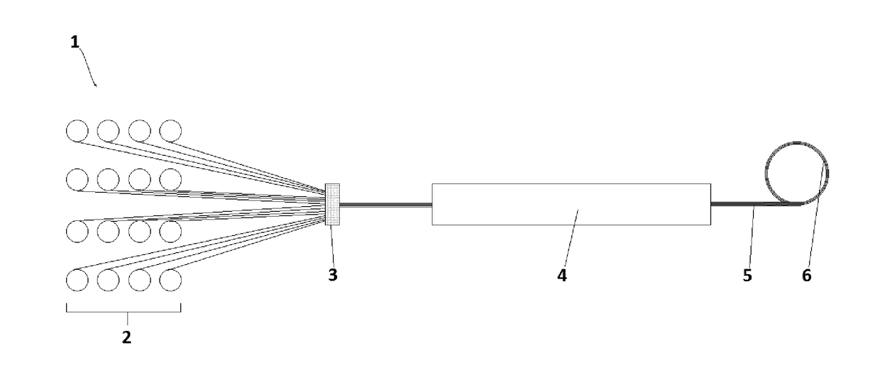
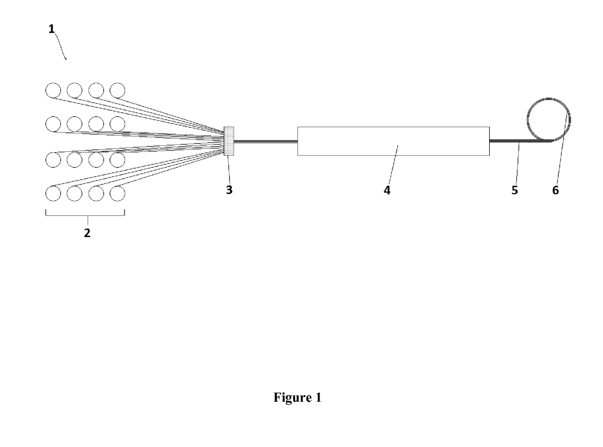
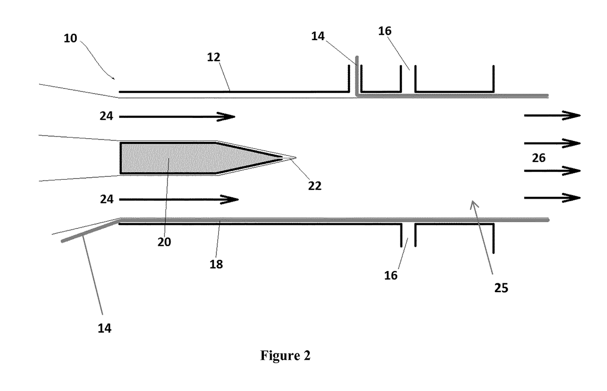
[0038]The pultrusion apparatus comprises a portion for receiving fibres, a portion for injecting resin into the fibres, a portion for impregnating the resin injected fibres, and a portion for shaping the impregnated fibres. The portions are preferably integrated. Preferably the portions are arranged so that fibres progress through the respective portions consecutively. We will now discuss more detailed aspects of each of these portions as follows.

[0039]Inlet, Inlet Plate or Spreader

[0040]Any fibre in the form of fibre tows comprising multiple filaments may be used in the pultrusion apparatus. Preferably, the fibre tows comprise carbon fibre tows. The receiving portion preferably comprises an inlet, or inlet plate or spreader. Preferably, the fibres in the form of tows are spaced and located in the receiving portion. The inlet for the pultrusion apparatus of the present invention comprises openings for receiving and locating the fibres in relation to subsequ...


PUM

PropertyMeasurementUnit
Fractionaaaaaaaaaa
Fractionaaaaaaaaaa
Fractionaaaaaaaaaa

Abstract

The present invention defines a pultrusion apparatus. The apparatus comprises a portion for receiving fibres, a portion for injecting resin into the fibres, a portion for impregnating the resin injected fibres, and a portion for shaping the impregnated fibres, wherein the fibres, following their passage through the receiving portion, converge in the resin injection portion to receive the resin and the resin flows outwards following injection as the fibres progress from the injection portion through the impregnation portion.

Description

FIELD OF INVENTION[0001]The invention relates to a pultrusion apparatus, an inlet or spreader for a pultrusion apparatus or process, a pultrusion process, a pultruded product and the use thereof, particularly but not exclusively the invention relates to an apparatus, inlet, process, and product including their uses for producing fibre reinforced pultrusion for use in wind energy applications such as wind turbine blades.BACKGROUND OF THE INVENTION[0002]Composite materials containing both a fibrous reinforcement material and a resin matrix or resin, have become of increasing importance. Such materials combine an excellent strength with a very low weight, which makes them the first choice for weight-sensitive applications, in particular in the aircraft and energy industries.[0003]There are numerous methods for the fabrication of composite structures, including but not limited to thermoforming polymeric matrices and autoclave processing. However, all are either labor intensive, more cos...

Claims


Application Information

Patent Timeline
IPC IPC(8): B29B15/12B29C70/52
CPCB29B15/122B29C70/523B29B15/12B29C70/52
Inventor MOSER, JOHANNESARCIDIACONO, MARCODE GIORGI, FRANCESCOGURU, VITHALDASHUNG, OWEN
Owner HEXCEL COMPOSITES GMBH & CO KG
Learn More