
Magneto-optical recording medium and method for reproducing information from a magneto-optical recording medium having three layers

Inactive Publication Date: 2005-12-20
CANON KK
View PDF23 Cites 0 Cited by
  • Summary
  • Abstract
  • Description
  • Claims
  • Application Information

AI Technical Summary

Benefits of technology

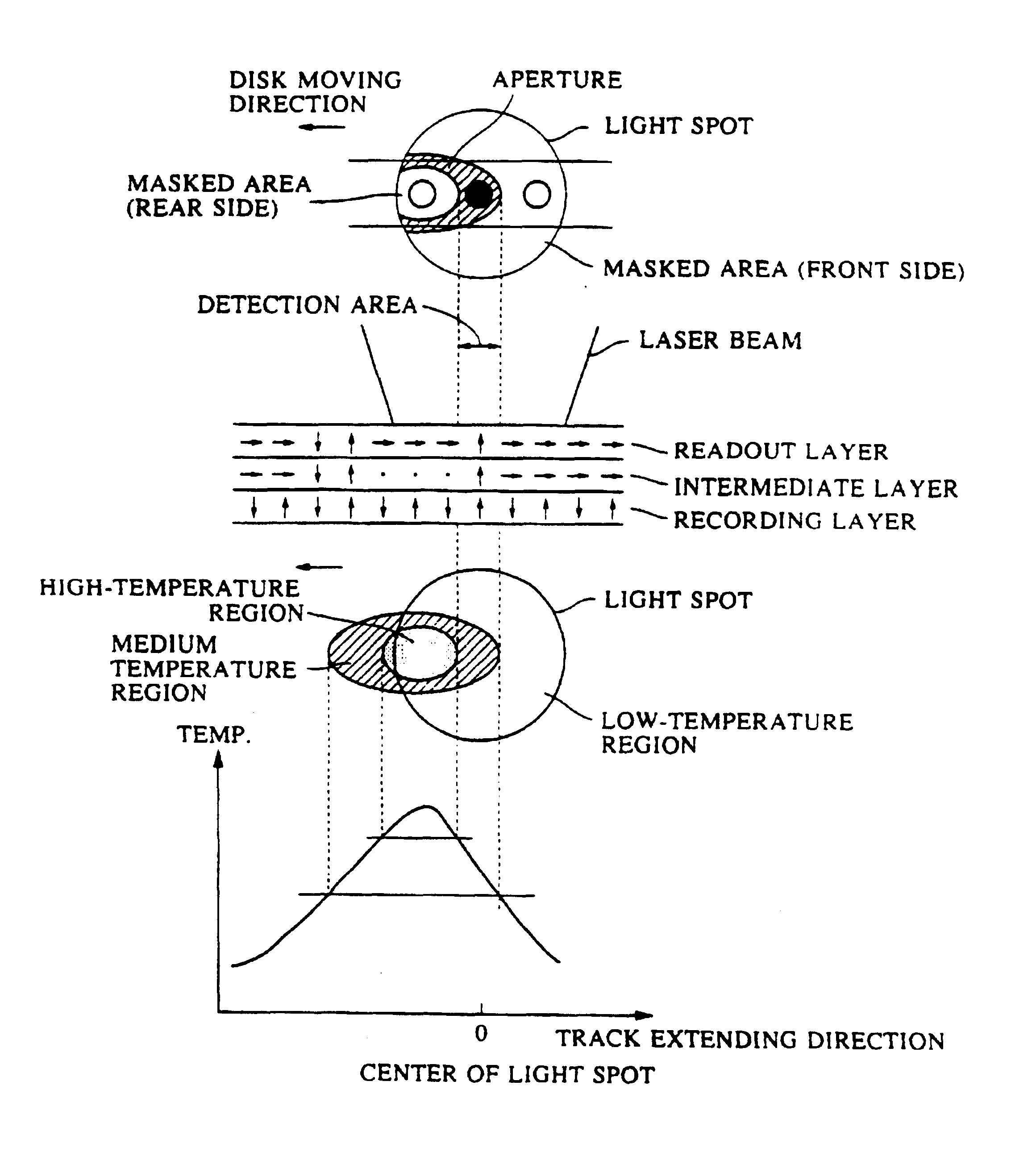
[0013]In consideration of the above problems, it is an object of the present invention to provide a magnetooptical recording medium which enables realization of high S / N reproduction of information recorded at a pitch below the diffraction limit of light with a simple structure, and a method for reproducing information using the recording medium.

Problems solved by technology

Track density of the optical disc is, on the other hand, chiefly limited by crosstalk.
However, there are limitations to improvement of the wavelength of a laser beam and the numerical aperture of an objective.
Due to such addition, problems arise, such as more complicated structure of a magnetooptical recording apparatus, difficulty of down-sizing, and higher cost of an apparatus.
It is thus difficult to stably provide a reproduction area having a predetermined space, and signal output is possibly decreased because the reproduction area is at the edge of the light spot.

Method used


Image

  • Magneto-optical recording medium and method for reproducing information from a magneto-optical recording medium having three layers
  • Magneto-optical recording medium and method for reproducing information from a magneto-optical recording medium having three layers
  • Magneto-optical recording medium and method for reproducing information from a magneto-optical recording medium having three layers

Examples


first experimental example

(First Experimental Example)

[0079]Targets Si, Tb, Gd, Fe, Co, Al and Cu were installed in a DC magnetron sputtering equipment, and a glass substrate was held on a holder. Thereafter, air was vacuum-exhausted from a chamber to establish a high vacuum level of less than 1×10⁻⁵ Pa by using a cryosorption pump.

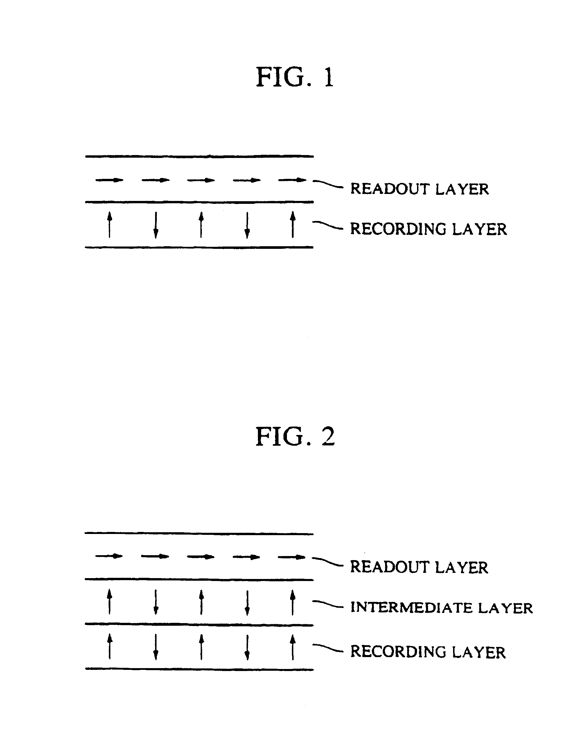
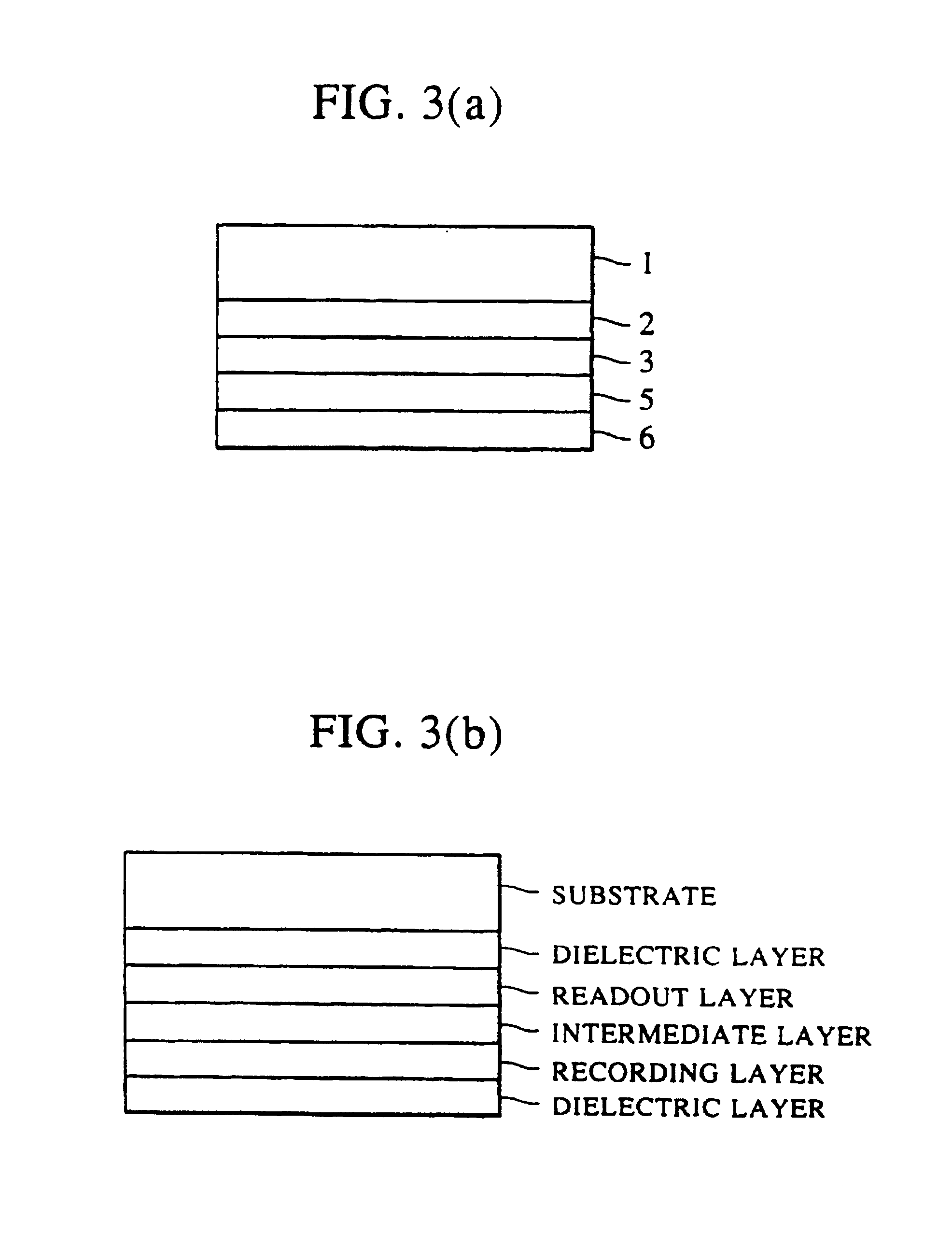
[0080]Ar gas was introduced into the chamber while vacuum-exhausting air, until the level of 0.3 Pa or Ar gas was reached. Then, a SiN layer, which functioned as an interference dielectric film, was deposited to a thickness of 700 Å on the surface of the substrate. A GdFeCo layer was (thickness: 400 Å) was deposited as a readout layer, and a TbFeCo layer (thickness: 400 Å) was deposited as a recording layer. Then, another SiN layer (thickness: 800 Å), which functioned as a protective dielectric film, was deposited to form a magnetooptical recording medium of the present invention having the two-layer structure shown in FIG. 3(a).

[0081]When the SiN layer was formed, N2 gas was intr...

second experimental example

(Second Experimental Example)

[0085]A magnetooptical recording medium was fabricated, which had the same layer structure as the above first example except that a polycarbonate substrate having a diameter of 130 mm and pregrooves was used.

[0086]Results of measurement of recording-reproducing characteristics of the magnetooptical recording medium were as follows. A measuring instrument comprised an objective lens of 0.55 N.A. and a projector for outputting a laser beam of 780 mm wavelength. Power for recording was preset at 8 mW, and linear velocity was 9 m / sec. Then, 6-15 MHz carrier signal was recorded in the recording layer by using a field modulation system in which a magnetic field of ±2000 e was applied stepwise. The dependency of C / N ratio on the recorded mark length was measured. The reproducing power was set to a value (2.5 to 3.5 mW) so that C / N ratio is maximized.

[0087]Table 1 shows the C / N ratios of the carrier signals recorded at 15 MHz (mark length: 30 μm), 11.25 MHz (mar...

third experimental example

(Third Experimental Example)

[0089]A magnetooptical recording medium of the present invention comprising a readout layer, a recording layer and an intermediate layer with low Curie temperature provided therebetween was fabricated and evaluated.

[0090]The same film forming instrument and film forming method as those employed in the second experiment example were used. A SiN layer as an interference dielectric layer was deposited to a thickness of 830 Å on the surface of a polycarbonate substrate having a diameter of 130 mm and pregrooves. A GdFeCo layer (thickness: 400 Å) was deposited as a readout layer, a TbFeCoAl layer (thickness: 100 Å) was deposited as an intermediate layer, a TbFeCo layer (thickness: 300 Å) was deposited as a recording layer. Then, another SiN layer (thickness: 700 Å) was deposited as a protective dielectric layer to form a magnetooptical recording medium having the structure shown in FIG. 3(b).

[0091]When the SiN layer was formed, N2 gas was introduced in additio...


PUM


Abstract

A magnetooptical recording medium has a first magnetic layer which is an in-plane magnetization film at both room temperature and high temperatures and changed to a perpendicular magnetization film at intermediate temperatures, and a second magnetic layer which is composed of a perpendicular magnetization film. The recording medium enables realization of high S / N reproduction of information recorded at a pitch below the diffraction limit of light with a simple structure, and further improvement in linear recording density and track density.

Description

[0001]ThisA division of the present reissue application was filed on Jan. 15, 2003 as reissue application Ser. No. 10 / 342,217. The present application is a reissue application of U.S. Pat. No. 5,831,944, which issued on Nov. 3, 1988 from application Ser. No. 08 / 858,206, filed May 13, 1997, now abandoned, which is a continuation of application Ser. No. 08 / 389,579 filed Feb. 15, 1995, now abandoned, which in turn is a continuation-in-part of application Ser. No. 08 / 111,974 filed Aug. 26, 1993, now abandoned in favor of continuation application Ser. No. 08 / 643,833 filed May 7, 1996, which issued as U.S. Pat. No. 5,626,428 on Apr. 1, 1997. <?insert-start id="INS-S-00003" date="20051220" ?>A division of said application Ser. No. 08 / 643,833 issued as U.S. Pat. No. 5,889,739, which is the subject of pending reissue application Ser. No. 09 / 820,734.<?insert-end id="INS-S-00003" ?>BACKGROUND OF THE INVENTION[0002]1. Field of the Invention[0003]The present invention relates to a m...

Claims


Application Information

Patent Timeline
IPC IPC(8): G11B11/00G11B11/105
CPCG11B11/10515G11B11/10584G11B11/10586
Inventor NISHIMURA, NAOKI
Owner CANON KK
Learn More