Long-range nozzle for entry of air

Inactive Publication Date: 2018-01-25
MERLIN TECH INC
View PDF5 Cites 2 Cited by
  • Summary
  • Abstract
  • Description
  • Claims
  • Application Information

AI Technical Summary

Benefits of technology

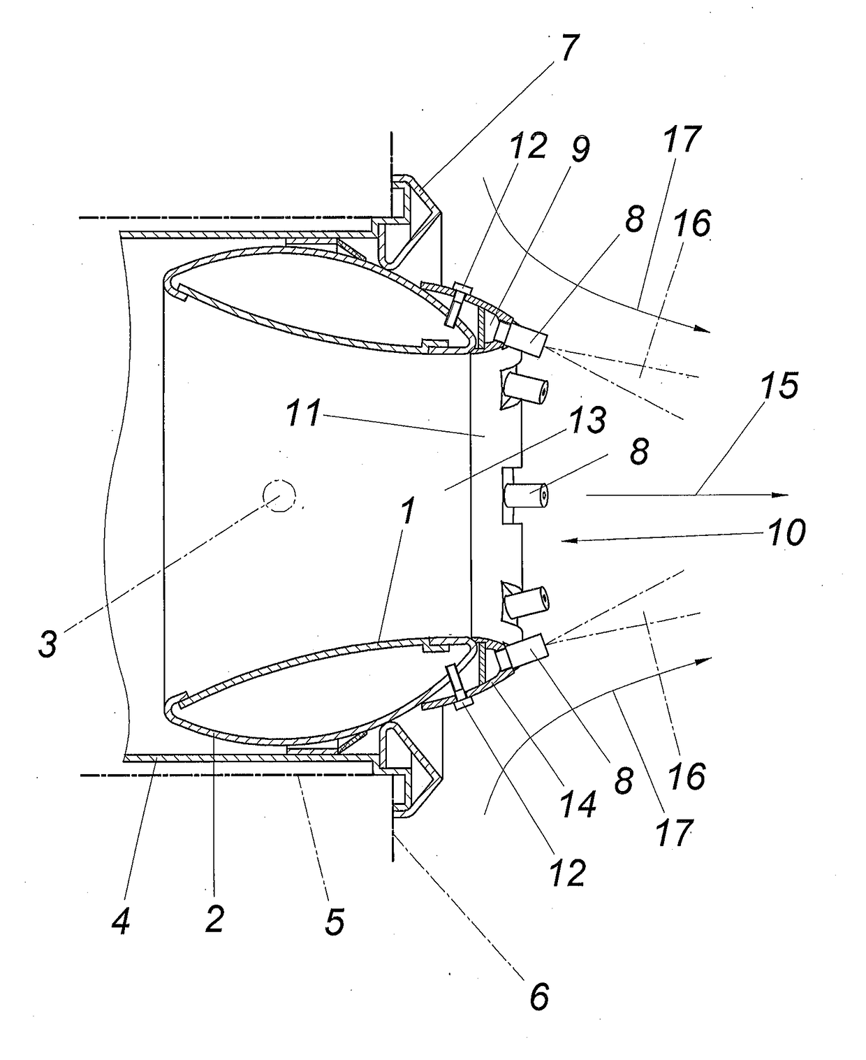
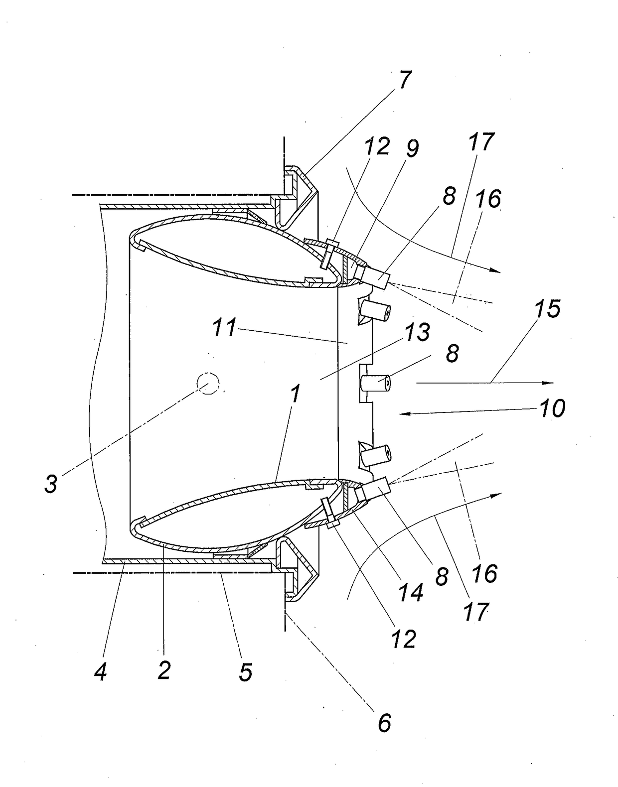
[0009]In order to improve the flow conditions for the air jacket surrounding the nozzle crown which is sucked in by an injector effect, an annular guiding wall can be provided on the side of the atomizer nozzles facing away from the nozzle opening which largely predefines the inflow conditions for this air jacket. If the atomizer nozzles are provided on a dome-shaped housing, a part of this housing can be advantageously used as guiding wall.
[0010]If the annular channe

Problems solved by technology

If the blown-in air directed into the room is to have a predefined moisture content, the air upstream of the long-range nozzle must be appropriately adjusted which is not only expensive but usually excludes a subsequent fitting with a moistening device.
The devices used for this purp

Method used


Image

  • Long-range nozzle for entry of air
  • Long-range nozzle for entry of air

Examples


Embodiment Construction

[0012]According to the exemplary embodiment shown, the long-range nozzle according to the invention comprises a conventional nozzle body 1 with a dome-shaped housing 2 which is pivotably mounted about a pivot axis 3 in a pipe connecting piece 4. The pipe connecting piece 4 via which the long-range nozzle is connected to an air line, is inserted in a recess 5, indicated by a dot-dash line, of a wall or ceiling 6 delimiting a room to be ventilated. The pipe connecting piece 4 with the dome-shaped housing 2 mounted in the pipe connecting piece 4 is covered by a terminating ring 7 which overlaps the wall or ceiling 6.

[0013]Unlike conventional long-range nozzles of this type, the long-range nozzle according to the invention is provided with a crown of atomizer nozzles 8 coaxial to the nozzle body 1 which are connected to an annular channel 9 which can be acted upon with a pressurized liquid for moistening the air blown out into the room. The atomizer nozzles 8 with the annular channel 9 ...


PUM


Abstract

A long-range nozzle for introducing air into a room comprising a nozzle body (1) opening in a nozzle opening (13) is described. In order to enable an advantageous air moistening, it is proposed that the nozzle opening (13) is surrounded by a coaxial crown of atomizer nozzles (8) which are connected to an annular channel (9) to which pressurized liquid can be applied.

Description

1. FIELD OF THE INVENTION[0001]The invention relates to a long-range nozzle for introducing air into a room comprising a nozzle body which opens in a nozzle opening.2. DESCRIPTION OF THE PRIOR ART[0002]Long-range nozzles are used for introducing cold or warm air into rooms with a required depth of penetration of the blown-out air flow in order in particular to supply a specific room area with the introduced air. The alignment of the long-range nozzles therefore acquires a considerable importance which has resulted in pivotably adjustable nozzle bodies. For this purpose it is known (EP 0 826 932 A2) to provide the substantially conical nozzle body with a dome-shaped housing which is mounted pivotably adjustably in a tubular connecting piece on the one hand about the axis of the connecting piece and on the other hand about an axis perpendicular thereto so that the nozzle opening protruding beyond the dome-shaped housing can be arbitrarily aligned. If the blown-in air directed into the...

Claims


Application Information

Patent Timeline
IPC IPC(8): F24F6/14B05B7/00
CPCF24F6/14B05B7/0075F24F2006/143F24F5/0035F24F13/065F24F2006/146Y02B30/54
Inventor REISINGER, JOHANN
Owner MERLIN TECH INC
Why Eureka
Try Eureka