Unlock instant, AI-driven research and patent intelligence for your innovation.
Target path generating device and driving control device
Active Publication Date: 2018-01-25
NISSAN MOTOR CO LTD
View PDF3 Cites 28 Cited by
Summary
Abstract
Description
Claims
Application Information
AI Technical Summary
This helps you quickly interpret patents by identifying the three key elements:
Problems solved by technology
Method used
Benefits of technology
Benefits of technology
The present invention provides a device that can generate a target pathway while reducing discomfort for the user. This device can detect objects near a curved path and avoid them without causing any discomfort to the user.
Problems solved by technology
However, if a sudden change is made to the driving of the vehicle in order to avoid the obstacle, an unexpected change for the user will occur in the behavior of the vehicle, and the user will feel discomfort in the ride quality.
Method used
Image
Click on the blue label to locate the original text in one second.
Reading with bidirectional positioning of images and text.
Examples
first embodiment
1. First Embodiment
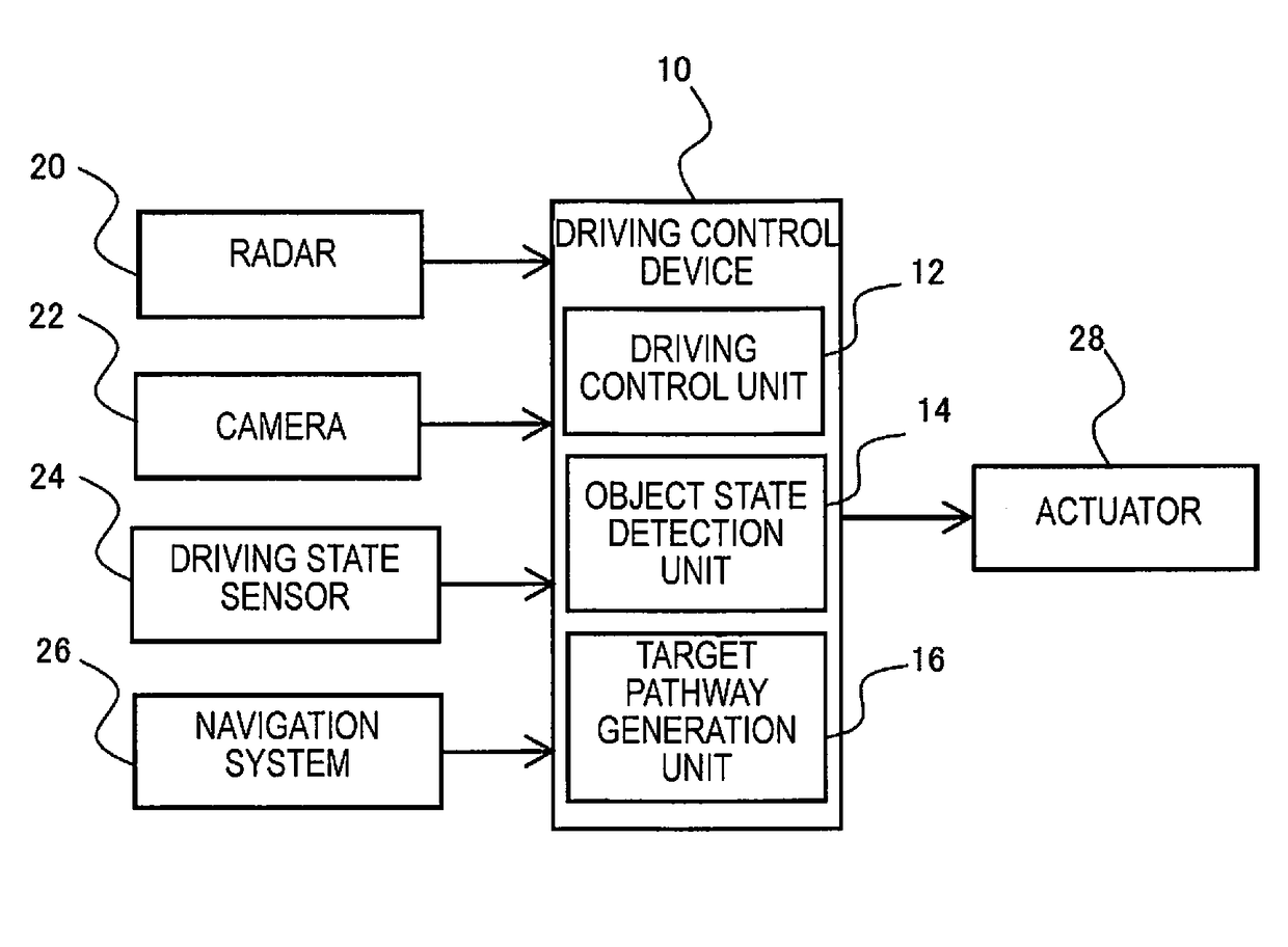
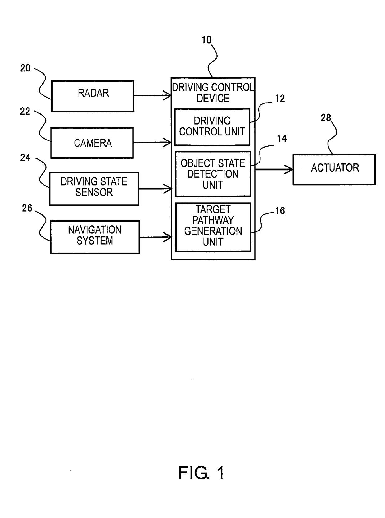
[0015]The configuration of the driving control device 10 according to the first embodiment will be described with reference to FIG. 1. FIG. 1 is a block diagram illustrating the configuration of the driving control device according to the first embodiment. The driving control device 10 is a device mounted in a vehicle, and is a device that controls the automatic driving of the vehicle.
[0016]Radar 20, a camera 22, a driving state sensor 24, a navigation system 26, an actuator 28, and the like, are electrically connected to the driving control device 10, as illustrated in FIG. 1. The driving control device 10 can be appropriately connected to other well-known configurations, such as a communication unit for carrying out inter-vehicle communication.
[0017]The radar 20 detects the presence, position, and speed, as well as the relative speed with respect to the host vehicle, of a vehicle, a motorcycle, a bicycle, a pedestrian, and the like, surrounding the host vehicle....
second embodiment
2. Second Embodiment
[0049]Next, the driving control device 10 according to the second embodiment will be described, with reference to FIG. 5 and FIG. 6. FIG. 5 is a flowchart illustrating the process of generating a target pathway for a curved path according to the second embodiment. FIG. 6 is a schematic view illustrating the road layout of a curved path and a target trajectory of the vehicle according to the second embodiment. In the second embodiment, the point relating to the generation of a target pathway, when a physical obstacle is present on the front side of a curved path 68 in the progress direction, within a predetermined range from the endpoint of the curved path 68, is different from the first embodiment. Configurations that are the same as the first embodiment are given the same reference symbols, and redundant descriptions are omitted.
[0050]In the second embodiment, an example will be described in which the map information acquired when generating a target pathway con...
example 1
(1) MODIFIED EXAMPLE 1
[0061]In the example described above, when a parking area 70 is present within a predetermined distance from the end position of the curved path 72, the vehicle change target pathway generating unit 36 sets a virtual area 74, and then recognizes the virtual area 74 as a physical obstacle, to reduce the generation of wobble in the trajectory of the target pathway. However, the invention is not limited to this example. For example, if a parking area 70 is present within a predetermined distance from the end position of the curved path 72, the target pathway from the parked vehicle 70 to the end position of the curved path 72 can be configured such that the margin from the end portion of the lane is set, for example, as an avoidance margin that is larger than the normal margin that is set in the map information. That is, upon determining that a parked vehicle 70 is present as an object to be avoided, a target pathway of the vehicle can be generated, which avoids a...
PUM
Abstract
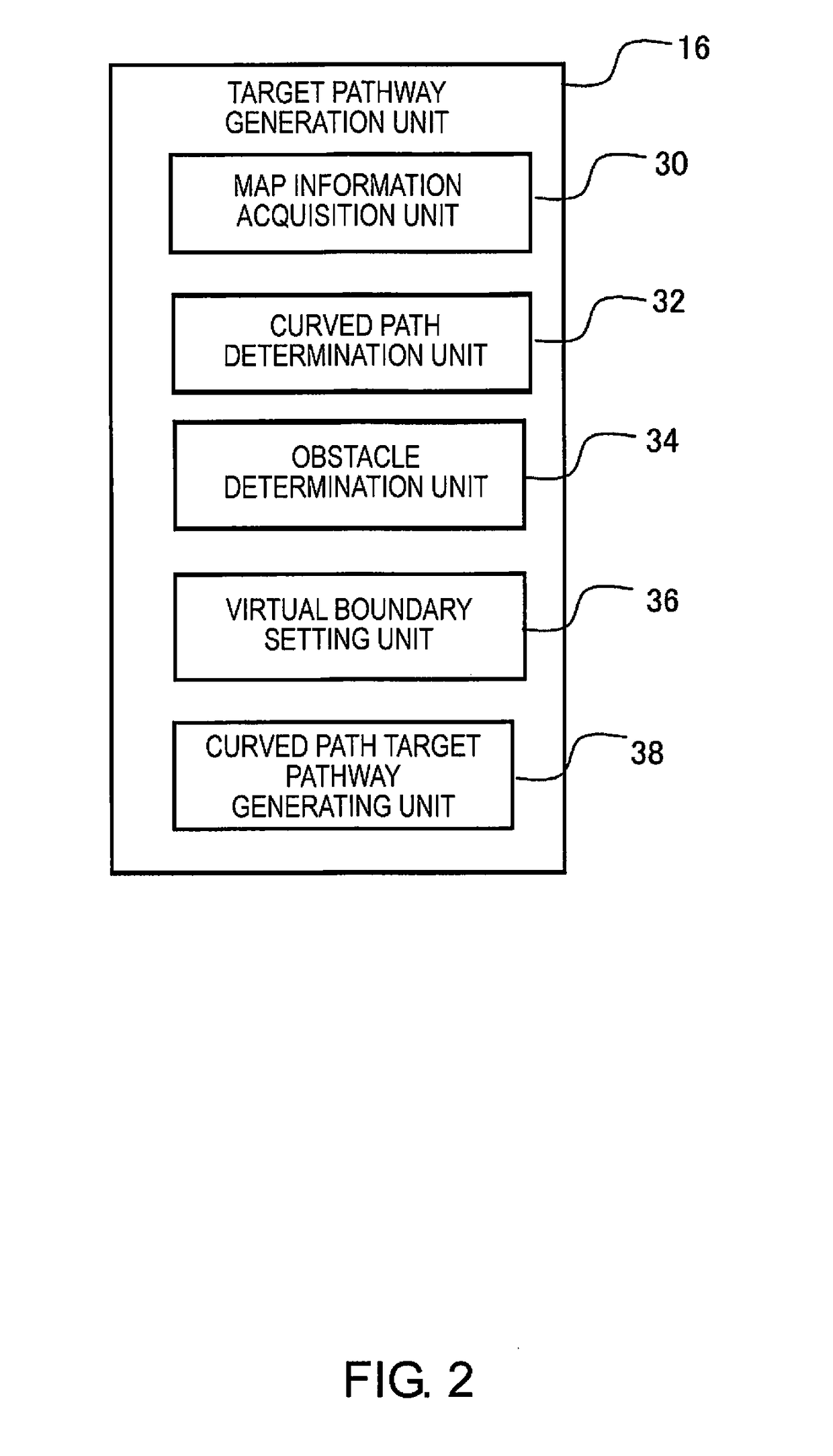
A target pathway generating device is provided with a map information acquisition unit, a curved path determination unit, an obstacle determination unit and a target pathway generating unit. The map information acquisition unit acquires map information. The curved path determination unit determines whether or not a curved path is present on a driving pathway of a vehicle based on the map information. Upon determining that a curved path is present, the obstacle determination unit determines whether or not there is an object to be avoided in the vicinity of the curved path. Upon determining that there is an object to be avoided, the target path generating unit generates a target pathway of the vehicle in order to avoid a predetermined region including the object to be avoided.
Description
TECHNICAL FIELD[0001]The present invention relates to a target pathway generating device and a driving control device. More specifically, the present invention relates to a target pathway generating device that generates a target pathway for controlling the driving of a vehicle, and a driving control device that comprises the target pathway generating device.BACKGROUND ART[0002]Attempts are being made to develop an autonomous driving control device that is capable of autonomously controlling a vehicle from a departure point to a destination (for example refer to Patent Document 1). In this type of autonomous driving control device, for example, a driving path of a vehicle from a departure point to a destination is calculated using a well-known navigation technique, and lanes and obstacles on the driving path are detected using sensing technology, such as a radar sensor, an image sensor, etc. The autonomous driving control device causes the vehicle to driving autonomously along a dri...
Claims
Application Information
Patent Timeline
Application Date:The date an application was filed.
Publication Date:The date a patent or application was officially published.
First Publication Date:The earliest publication date of a patent with the same application number.
Issue Date:Publication date of the patent grant document.
PCT Entry Date:The Entry date of PCT National Phase.
Estimated Expiry Date:The statutory expiry date of a patent right according to the Patent Law, and it is the longest term of protection that the patent right can achieve without the termination of the patent right due to other reasons(Term extension factor has been taken into account ).
Invalid Date:Actual expiry date is based on effective date or publication date of legal transaction data of invalid patent.
