
Electrical device installation monitoring improvement

a technology for installing monitoring and electrical devices, applied in the integration of power network operation systems, tariff metering apparatuses, sustainable buildings, etc., can solve the problems of not being considered as appropriate electrical equipment for electrical devices such as lamps or toasters, devices in standby mode,

Inactive Publication Date: 2018-01-25
EMBERTEC
View PDF6 Cites 3 Cited by
  • Summary
  • Abstract
  • Description
  • Claims
  • Application Information

AI Technical Summary

Benefits of technology

This patent describes an energy saving device that can be installed in a premise to measure and verify energy savings. The device includes a communication module that sends a verification code to a monitoring entity upon installation. The unique identifier of the device is combined with the geographical location of the premise to create a verification code. The device can be connected to a power outlet and an electrical device, and a testing means monitors the power drawn to determine if the installation is correct. The device also periodically sends a verification code to the monitoring entity to verify continued operation. The technical effect of this patent is to provide a more accurate measurement and verification of energy savings, which can be useful for incentive payments and continued operation of the device.

Problems solved by technology

Users of such devices typically leave the device in standby mode for lengthy periods of time, without considering the power use in the standby power state.
Not every possible installation of the devices will be likely to bring about power savings.
Electrical devices such as lamps or toasters may not be considered as appropriate electrical equipment due to their infrequent use for long periods of time and / or their lack of a standby power state.
A shortcoming in such incentive schemes is that the entity providing the incentive has great difficulty in verifying that the energy saving devices have been installed in the appropriate manner and are able to provide a reduction in energy usage.
Such incentive schemes are open to exploitation as there is no present way available to positively verify correct installation and ensure that the energy saving device is in active use and capable of saving or reducing energy consumption apart from undertaking a physical audit of installations.
Such audits are expensive and time consuming and therefore it is not viable to audit every installation that has been undertaken.
The result is a low level of confidence that the energy saving devices have actually been installed and installed correctly.

Method used


Image

  • Electrical device installation monitoring improvement
  • Electrical device installation monitoring improvement
  • Electrical device installation monitoring improvement

Examples


Embodiment Construction

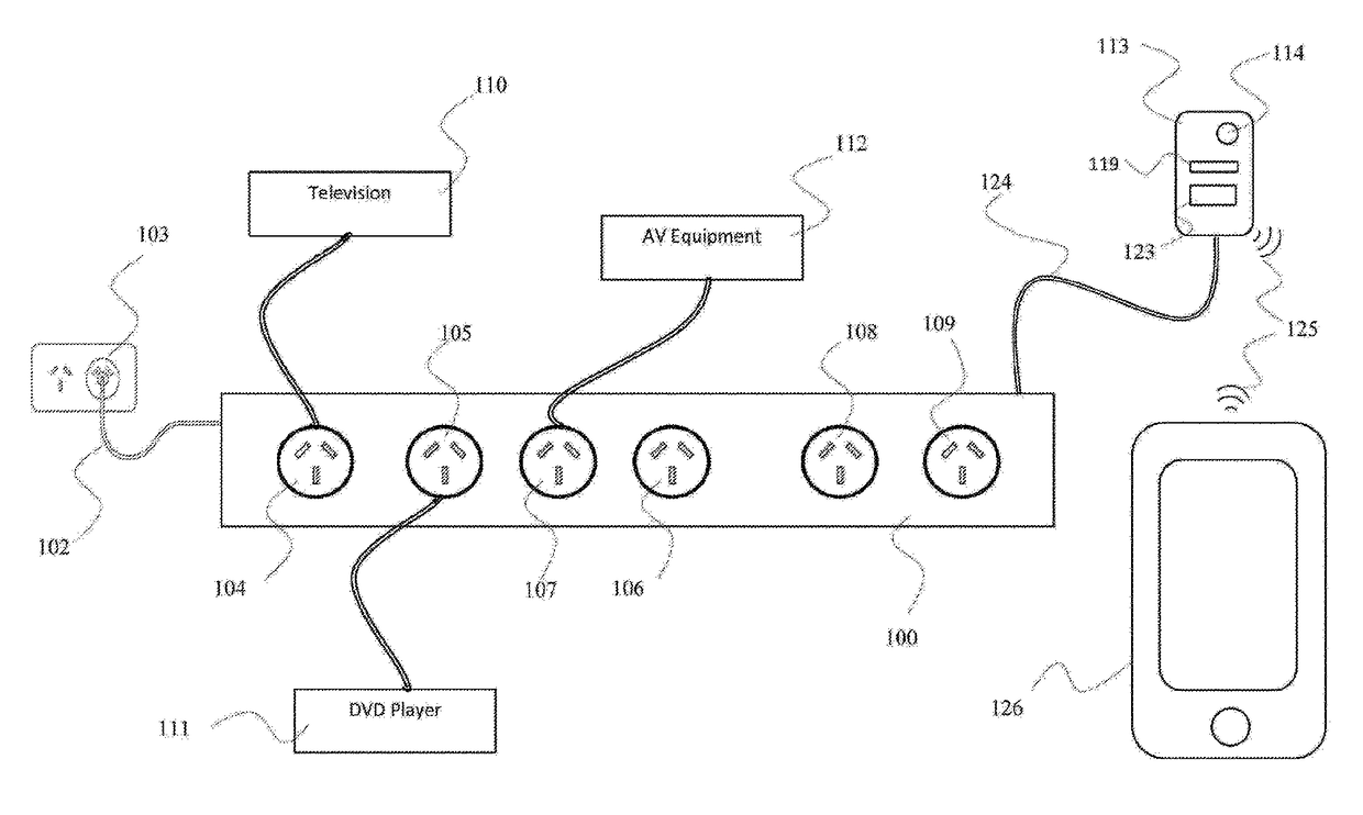
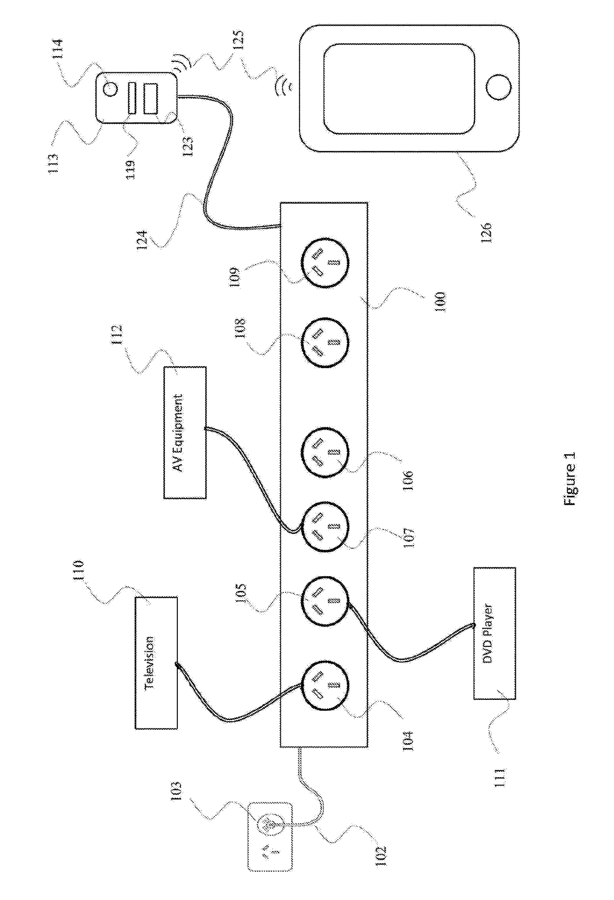
[0038]Referring first to FIG. 1, it is to be understood that this is a general representation of an installation including a standby power controller (SPC) including the invention and is illustrative only. It is not intended to limit the number or configuration of continually powered or switched or monitored main outlets, or of communication interfaces or other functional modules.

[0039]FIG. 1 shows a representation of an energy saving device in the form of an SPC. An SPC is an energy saving device which is installed in between the mains power supply and an electrical device. For example, it is common that electrical devices such as AV equipment and computer equipment are “turned off” by being changed to a standby power state, which reduces, but does not eliminate, power consumption. Energy savings may be achieved by powering these types of devices by plugging them into an SPC. In some instances one of these attached electrical devices may be considered to be the main device, in that...


PUM


Abstract

An energy saving device for installation in a household, the energy saving device including′ a communications module used to transmit identification data and usage data to a monitoring entity for energy savings measurement and verification purposes. The identification data includes a unique identifier o of the energy saving device. The unique identifier is combined, with a geographical location of the premises to form a verification code.

Description

FIELD OF THE INVENTION[0001]The present invention relates to an apparatus and method for the verification of installation of electrical equipment, in particular verification acceptable to a party not being an installer of the electrical equipment.BACKGROUND[0002]When a user installable electrical device is installed typically the device is plugged into a suitable outlet that is connected to the mains electrical supply. This is usually a wall outlet, sometimes referred to as a general purpose outlet (GPO), but can also be a power extension board or similar. Verification of the installation, if required, requires no more than the observation, by the installer, that the most basic functions of the device are operational.[0003]Most current electrical devices, and in particular computer and audio visual (AV) devices have a number of power states, such as on, off and standby. The standby power state is one that keeps the electrical device powered to be able to receive a signal, such as a ...

Claims


Application Information

Patent Timeline
Patent Type & Authority Applications(United States)
IPC IPC(8): H02J9/00G05B15/02H04L29/06H02J13/00
CPCH02J9/005H02J13/0075G05B15/02H04L63/0876H04L63/126H01R25/003Y04S20/242G01D4/006Y02B70/30Y02B90/20Y04S40/126Y04S20/20Y04S20/30
Inventor GELONESE, DOMENICOGATTO, RICCARDO
Owner EMBERTEC
Learn More