Squirrel-cage rotor, and asynchronous motor comprising such a rotor

Active Publication Date: 2018-01-25
GE ENERGY POWER CONVERSION TECH
View PDF0 Cites 15 Cited by
  • Summary
  • Abstract
  • Description
  • Claims
  • Application Information

AI Technical Summary

Benefits of technology

[0009]In accordance with further aspects of embodiments of the invention, the rotor comprises one or more of the following features, taken individually or in any technically feasible combination: the short-circuit cage comprises a second electrical short-circuit ring, the or each bar having a second end part, the second end

Problems solved by technology

However, the free arrangement of the ends of the bars in the orifices formed in the short-circuit rings does not make it possible to guarantee electrical contact under all conditions of use, in particular for low speeds of ro

Method used


Image

  • Squirrel-cage rotor, and asynchronous motor comprising such a rotor
  • Squirrel-cage rotor, and asynchronous motor comprising such a rotor
  • Squirrel-cage rotor, and asynchronous motor comprising such a rotor

Examples


second embodiment

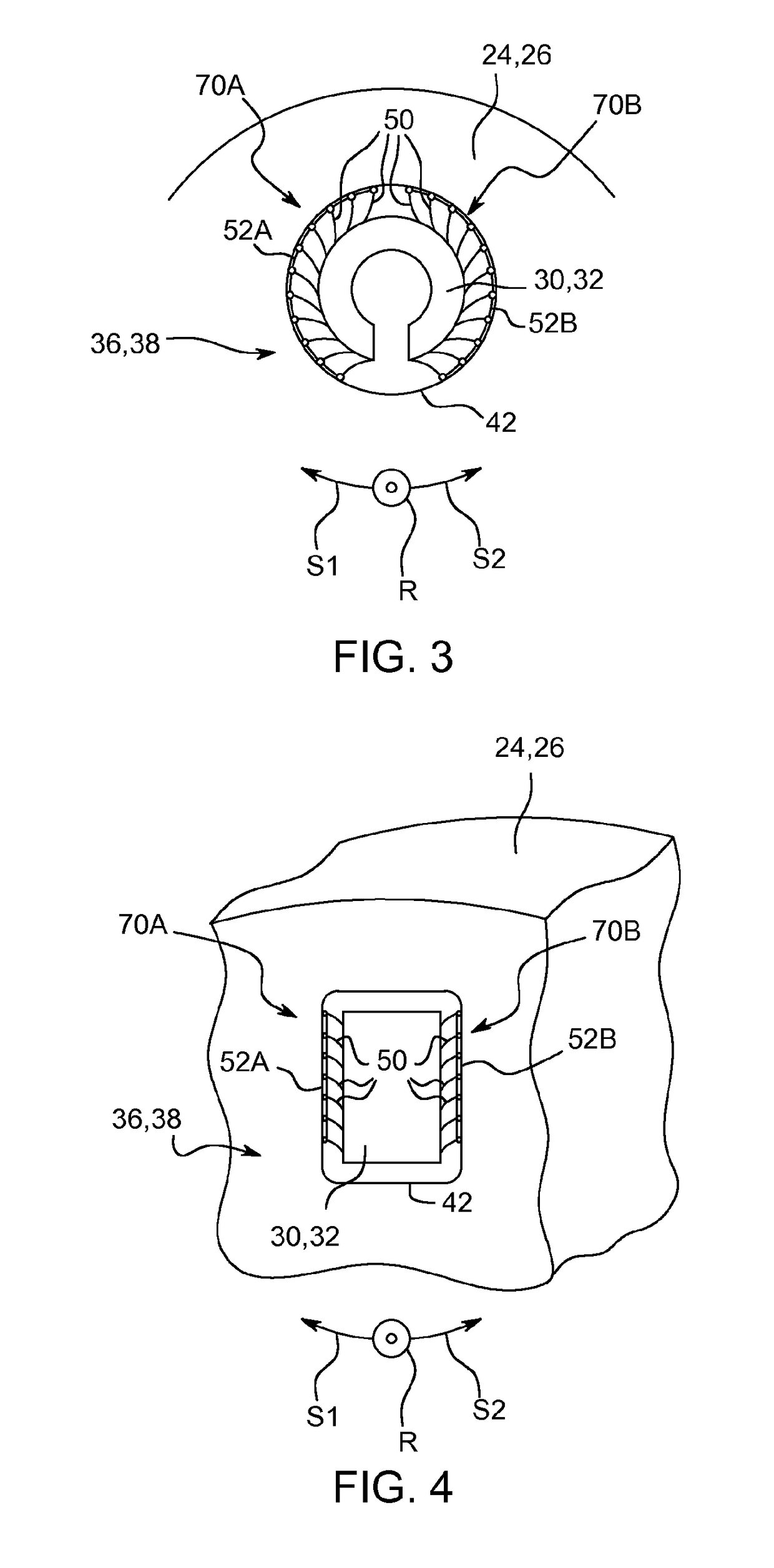
[0066]In accordance with this second embodiment at least one connection means 36, 38 comprises a bushing 80, a first group 82 of flexible blades, and a second group 84 of flexible blades, the blades 50 being electrically conductive and connected to the bushing 80. The first group of blades 82 is received at the outer periphery of the bushing 80 and in abutment against the respective short-circuit ring 24, 26, and the second group of blades 84 is received at the inner periphery of the bushing 80 and in abutment against the respective end part 30, 32 of the corresponding bar 28.

[0067]The bushing 80 has, in the plane transverse to the axis of rotation X-X′, a section of shape substantially identical to that of the section of the outer part 30, 32 in said transverse plane.

[0068]The bushing 80 is for example in the shape of a cylinder when the corresponding end part 30, 32 has a substantially circular section.

[0069]In an additional variant (not shown) at least two first groups 82 of blad...

third embodiment

[0076]In accordance with this third embodiment the flexible blades 50 of a respective connection means 36, 38 are received in a hollow 90 formed in the respective end part 30, 32 of the corresponding bar 28 and in abutment against the respective short-circuit ring 24, 26.

[0077]The hollow 90 comprises a base 92 and two radial walls 94. The flexible blades 50 are held in the hollow 90 for example with prestress, being applied against the radial walls 94. In the unstressed state of the blades 50, the central part 60 thereof extends outside the hollow 90 and is in abutment against the corresponding short-circuit ring 24, 26.

[0078]In a variant the flexible blades 50 are glued in the hollow 90 and do not require any prestress in the absence of the short-circuit ring 24, 26. In this case, in the absence of the short-circuit ring 24, 26, the blades 50 are not in contact with the radial walls 94.

[0079]In addition, the connection means 36, 38 comprise at least one stop 96 suitable for limitin...

first embodiment

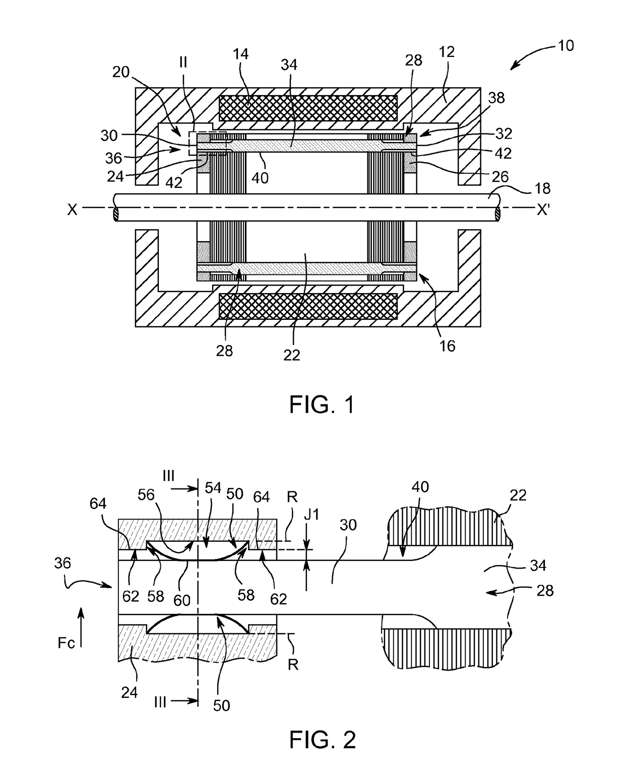
[0082]In this state, the end part 30, 32 and the associated short-circuit ring 24, 26 form a clearance J2 (FIG. 6) enabling a displacement radially outwardly of the end part 30, 32 against the force of some of the blades 50. The clearance J2, similarly to the clearance J1 of the first embodiment, between the stop 96 with its wall 98 and the short-circuit ring 24, 26 limits the radial displacement of the end part 30, 32 under the centrifugal force Fc, thus limiting the stresses in the bar 28 and the blades 50.

[0083]Is thus understood that the rotor 16 of the electric machine 10 according to embodiments of the invention makes it possible to improve the electrical contact between the conductive bars 28 and the rings 24, 26 of the short-circuit cage 20, moreover for a very wide range of rotational speeds of the rotor 16, ranging from standstill to very high rotational speeds, for example from 3,000 revolutions per minute to 20,000 revolutions per minute.


PUM


Abstract

An electric machine rotor, which extends along an axis of rotation, including a short-circuit cage, the or each first connection means between a respective first end part of the or each bar and the first short-circuit ring includes a plurality of flexible electrically conductive blades.

Description

BACKGROUND OF THE INVENTION[0001]Embodiments of the present invention relate to a rotor for an electric machine, extending along an axis of rotation and comprising a short-circuit cage having at least one bar and at least one first electrical short-circuit ring, the or each bar having a first end part, the first end part being connected to the first short-circuit ring electrically by a first connection means and radially with respect to the axis of rotation.[0002]Embodiments of the present invention also relate to an electric machine, in particular an asynchronous machine, particularly a motor, comprising a stator and a rotor of this type.[0003]A rotor of the aforementioned type is known from document EP 0 628 675 A1.[0004]The rotor comprises a magnetic mass extending along the axis of rotation and a short-circuit cage. The short-circuit cage comprises two short-circuit rings placed on either side of the magnetic mass along the axis of rotation and a plurality of electrically conduc...

Claims


Application Information

Patent Timeline
IPC IPC(8): H02K17/16
CPCH02K17/165
Inventor GALMICHE, CHRISTOPHEHUMBERT, PIERREKLINGER, CHRISTOPHE
Owner GE ENERGY POWER CONVERSION TECH
Why Eureka
Try Eureka