
Seat illuminating system

a technology of illumination system and seat, which is applied in the direction of storage device, superstructure subunit, lighting and heating apparatus, etc., can solve the problems of increasing stress, anxiety, and discomfort caused, and even increasing stress

Active Publication Date: 2018-02-01
COELUX
View PDF5 Cites 9 Cited by
  • Summary
  • Abstract
  • Description
  • Claims
  • Application Information

AI Technical Summary

Benefits of technology

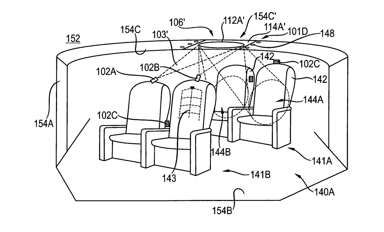
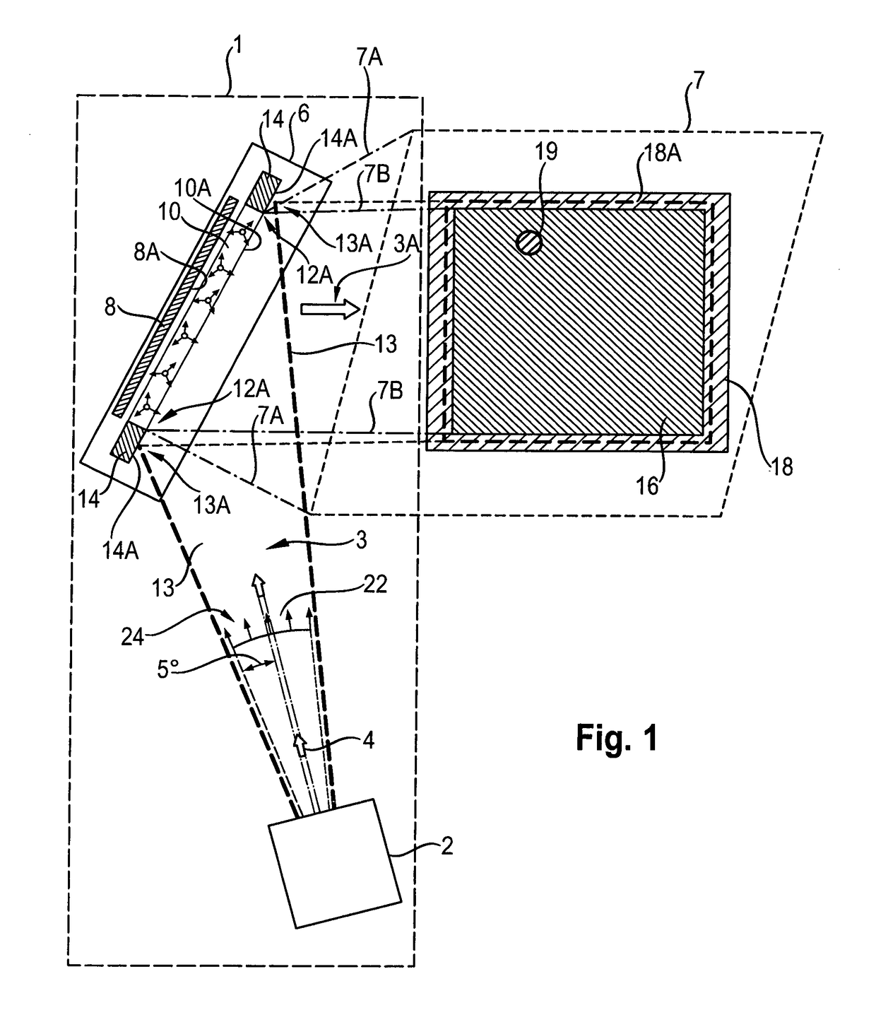
The present disclosure is about a seat illuminating system for vehicles such as cars, buses, trains, or airplanes. The system includes a seat arrangement with a seat surface and a target region for a person sitting on the seat. A mounting structure is fixed to the seat arrangement and a reflector unit is mounted at the mounting structure. The reflector unit has a reflective surface and a luminous layer for emitting diffuse light at a first color. A light projector generates a light beam that passes through the luminous layer and is reflected by the reflective surface before and after being reflected by the luminous layer. The light beam is directed onto the target region to illuminate it. The system can be used in passenger cabins of transportation units and provides a comfortable and pleasant atmosphere for passengers.

Problems solved by technology

In a cabin of a vehicle such as a train, an aircraft, or a cars as well as in a closed, confined, indoor ambience, one may experience discomfort caused by the reduce ability to move, and the perception of the confined environment.
Often, only a limited view or no view at all may increase stress, fatigue, and even anxiety.

Method used


Image

  • Seat illuminating system
  • Seat illuminating system
  • Seat illuminating system

Examples


Embodiment Construction

[0034]The following is a detailed description of exemplary embodiments of the present disclosure. The exemplary embodiments described therein and illustrated in the drawings are intended to teach the principles of the present disclosure, enabling those of ordinary skill in the art to implement and use the present disclosure in many different environments and for many different applications. Therefore, the exemplary embodiments are not intended to be, and should not be considered as, a limiting description of the scope of patent protection. Rather, the scope of patent protection shall be defined by the appended claims.

[0035]The disclosure is based in part on the realization that one may addresses the problem of discomfort when sitting in confined ambiences by a lighting approach that provides an enhancement of depth perception and an increase of the visual comfort by an optical widening of confined ambience.

[0036]In particular, it was realized that linking and coupling an illuminatio...


PUM


Abstract

A seat illuminating system (101D) for, in particular sunlight-like, illuminating a target region (144) comprises a seat arrangement (140) having a seat surface (142A). The target region (144) is defined for a person sitting on the seat surface (142A). The seat illuminating system (101D) comprises further a mounting structure (150A) being spatially fixed with respect to the seat arrangement (140); a reflector unit (106) mounted at the mounting structure (150A) and comprising a reflective surface and a luminous layer for homogenously emitting diffuse light at a first color, the luminous layer extending in front of the reflective surface and comprising a visible front area section (110A) of the reflector unit (106). The seat illuminating system (101D) comprises further a light projector (102) mounted at the mounting structure (150A) and configured to generate a light beam (103) adapted in size for comprehensively illuminating the visible front area section (110A) such that at least a portion of the light beam (103) passes through the luminous layer before and after being reflected by the reflective surface, thereby forming an illuminating light beam (103A) at a second color directed onto the target region (144).

Description

TECHNICAL FIELD[0001]The present disclosure relates generally to illumination systems, in particular to seat illuminating systems for optically imitating natural sunlight illumination and in particular to combinations of seat illuminating systems with a widened perception / impression of the ambient space.BACKGROUND[0002]Illumination systems are often provided for seat arrangements such as seats in a car, train, or airplane to, for example, provide a seat specific reading illumination.[0003]In a cabin of a vehicle such as a train, an aircraft, or a cars as well as in a closed, confined, indoor ambience, one may experience discomfort caused by the reduce ability to move, and the perception of the confined environment. This applies, for example, also to situations, where one has to remain or to wait for a significant amount of time in a sitting position on a chair, armchair, a seat, or a recliner such as in waiting rooms, workstations and the like. Often, only a limited view or no view ...

Claims


Application Information

Patent Timeline
Patent Type & Authority Applications(United States)
IPC IPC(8): B60Q3/233B60Q3/51B60Q3/56B60Q3/64B60Q3/44F21V7/06B60Q3/74B60R13/02B60Q3/208F21V14/04F21V7/00B60Q3/43B60Q3/82
CPCB60Q3/233B60Q3/43B60Q3/51B60Q3/56B60Q3/64B60Q3/44B60Q3/82B60Q3/745B60R13/02B60Q3/208F21V14/04F21V7/0008F21V7/06B60R2013/0287B64D11/00B64D2011/0038B64D2011/0053B64D11/003B61D29/00F21V7/05
Inventor DI TRAPANI, PAOLOMAGATTI, DAVIDE
Owner COELUX
Learn More